jib77
0
- Joined
- Jun 19, 2010
- Messages
- 718
- Points
- 0
I deleted it because what I had posted was wrong.
I though V- and GND were still common, and they are not.
I though V- and GND were still common, and they are not.


")
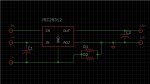
ANY non-floating reference ICs cannot work like the 317.
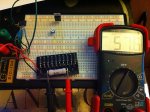
All values were calculated with a 22ohm 1/2W 5% resistor

Voltage supplied (V):	Test load (V):	Output (mA):
6V	                        4.2V	                57.5mA
8.4V	                        4.2V	                57.6mA
4.1V	                        4.2V	                15mA

4.1V	                        2.8V	                56.5mA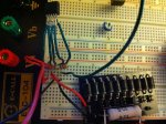
8.4V 2.8V 57.4mAVoltage supplied (V) Test load (V) Output (A)
@ 1ohm
8.15V 2.8V 1.24A
@ (2) 1ohm resistors in parallel = .5ohm
8.15V 2.8V 1.93A
8.15V 4.2V 1.22A