Welcome to Laser Pointer Forums - discuss green laser pointers, blue laser pointers, and all types of lasers

LPF Donation via Stripe | LPF Donation - Other Methods

Links below open in new window

ArcticMyst Security by Avery

Inverting buck/boost - Case Positive Diode Driver

rhd

0
Joined
Dec 7, 2010
Messages
8,475
Points
0
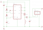
Inverting buck / boost drivers have always hurt my head, but as I think about it, I'm starting to wonder whether this variant if switching driver may actually be the solution for case positive diodes.

400px-Buckboost_operating.svg.png


The V- essentially becomes continuous with the LD+, even though technically they're never part of the same closed circuit. Out seems to me that you could have the LD+ attached to the host, and the host would actually be tailcap negative (which sounds strange, I realize).

What am I missing? Wouldn't this work?
 
Last edited:


djQUAN

0
Joined
May 27, 2013
Messages
1,154
Points
63
Re: Inverting buck/boost - is this the easy answer for case positive diodes?

It will work but the current control loop / current sense IC would be a nightmare unless you figure out a neat trick or something.
 

rhd

0
Joined
Dec 7, 2010
Messages
8,475
Points
0
Re: Inverting buck/boost - is this the easy answer for case positive diodes?

It will work but the current control loop / current sense IC would be a nightmare unless you figure out a neat trick or something.

And here's the neat trick I'm thinking of:

attachment.php


Long story short, we buck in constant voltage mode, using the approach the boost/buck IC is expecting rather than trying to make inverted current sensing work (which I hurt my brain trying to problem solve, and didn't end up with a workable solution to). Rather, we get current control via a continuous-positive linear like an AMC7135, after the fact. Bucking to 3.75V gives us efficiency so that the linear is just doing a little bit of work controlling current.
 

Attachments

  • schem.png
    schem.png
    6.5 KB · Views: 725

djQUAN

0
Joined
May 27, 2013
Messages
1,154
Points
63
Re: Inverting buck/boost - is this the easy answer for case positive diodes?

Yes I think that would work. Although I think there should be a pot to adjust output voltage to be able to trim off right at the dropout voltage and the differences in diodes.
 

rhd

0
Joined
Dec 7, 2010
Messages
8,475
Points
0
Yes I think that would work. Although I think there should be a pot to adjust output voltage to be able to trim off right at the dropout voltage and the differences in diodes.

I'll add that.

Unfortunately, AMC7135s don't scale well, you just have to keep adding more, so this approach becomes bulky at higher currents. I thought about adding the traditional MOSFET + transistor current source, but that adds a 0.7V drop.

EDIT: Here's a first pass at a board. It's proof of concept only (large, only setup for 350mA). But if it works, then at least we have a boost-buck driver that can run case positive diodes, and can scale up to 5A or so before size becomes too obnoxious. If it works and people use it, it's going to drive everyone nuts that they'll be attaching the battery (-) to their tailcap, even though the diode is case (+). I'd expect a lot of confused forum posts!

attachment.php


attachment.php
 

Attachments

  • board.png
    board.png
    32.3 KB · Views: 483
  • schem.png
    schem.png
    6.2 KB · Views: 558
Last edited:

djQUAN

0
Joined
May 27, 2013
Messages
1,154
Points
63
Looks good.

Scale up to 5A? that's a lot of AMC chips in parallel :p

With the same PCB, it may be possible to get 700mA by putting another right on top of the existing AMC chip. Or even 1050mA if you're adventurous :)
 

rhd

0
Joined
Dec 7, 2010
Messages
8,475
Points
0
Does anyone know how the AMC7135 internally works such that the voltage drop can get so low? Can we replicate that? I thought about using a MOSFET current regulator schematic but swap the transistor for a germanium transistor so that it wouldn't drop 0.7V. But it turns out germanium transistors are hard to find in SMD.
 
Joined
Jan 14, 2009
Messages
1,452
Points
83
looking at the data sheet , in the basic diagram it uses a very low resistance N channel mosfet as the pass item

I have no idea about the switching regualtor stuff but Could you use a LDO controller and a external pass mosfet to give you the low dropout regualtor your after , ideally the same as the 7135 but with a external mosfet ( with higher current capability ) ?
 
Last edited:

rhd

0
Joined
Dec 7, 2010
Messages
8,475
Points
0
I wonder if this works? Everything about it looks wrong, but I think it might work given that the the final output portion is linear regulation... why not regulate on the (-) rail of the LD output.

attachment.php
 

Attachments

  • schem.png
    schem.png
    6.6 KB · Views: 494
Last edited:

Benm

0
Joined
Aug 16, 2007
Messages
7,896
Points
113
The general concept of using a switchmode driver with negative voltage output does work, which would solve problems driving 808nm pump diodes in hosts where the negative battery terminal is connected to the case.

There is little need to complicate things by using an inverter first and following that up by some sort of linear driver.

As far as dropout voltages go: the can be very low of a negative-side driver like 7135: no need to overcome the B-C voltage of 0.7 volts at all, only the E-C voltage is in the way which could be as low as 0.2-0.3 volts for a bipolar silicon transistor, and near zero for a FET.
 

rhd

0
Joined
Dec 7, 2010
Messages
8,475
Points
0
There is little need to complicate things by using an inverter first and following that up by some sort of linear driver.

That's good news. I look forward to your thoughts on how to achieve current regulation without the linear driver tagged on the end. That's what I struggled with.
 

Hiemal

0
Joined
Dec 27, 2011
Messages
1,443
Points
63
Alternatively, if current sensing is an issue to begin with, why not just flip the ZXCT around so that it still gets a "positive" current measurement to read?

It shouldn't know the difference, since it's just a matter of making sure it gets to read a positive potential relative to ground. Then you could just make it like any other switchmode CC driver, without having to add the additional bulk of a LDO or linear or another transistor.
 

rhd

0
Joined
Dec 7, 2010
Messages
8,475
Points
0
Alternatively, if current sensing is an issue to begin with, why not just flip the ZXCT around so that it still gets a "positive" current measurement to read?

It shouldn't know the difference, since it's just a matter of making sure it gets to read a positive potential relative to ground. Then you could just make it like any other switchmode CC driver, without having to add the additional bulk of a LDO or linear or another transistor.

It sounds great, and that's what I initially thought of doing, but start trying to actually implement that, and you'll see that there's no way to drop it into the the inverter circuit such that it doesn't interrupt the V- / LD+ common connection, and creates a voltage at the IC's FB pin that is 1.25 (or 0.8 or 0.6, or whatever the FB voltage is) above the IC's ground.

Give it a shot. You may have more luck than I, but I don't think it's as straight forward as you've suggested.
 
Last edited:

djQUAN

0
Joined
May 27, 2013
Messages
1,154
Points
63
The challenge with that IC is that it disrupts the common (+). The AMC doesn't, which is why it works well here. I can't see a way to make that Linear chip common positive.

The LED driver in the examples page is continuous positive.

attachment.php
 

Attachments

  • led.png
    led.png
    11.2 KB · Views: 863


Top