Welcome to Laser Pointer Forums - discuss green laser pointers, blue laser pointers, and all types of lasers

Buy Site Supporter Role (remove some ads) | LPF Donations

Links below open in new window

FrozenGate by Avery

how to make analog modulation ?

Joined
Jul 8, 2012
Messages
103
Points
18
hey guy
I want to buy this module

RGB 800mW Laser Module White Beam Combined BY638NM 532nm 450NMANALOGO Modulation | eBay

i don't think I known how to make an analog modulation.
I thought I could use 3 1k pots , 3 2.5k resistances in parallel , 3 237ohms resistances and 2 18650 batteries to make a 0 5v variable power supply.
i know I won't go under v1.25 with lm 317.
34hvz1f.jpg


2pqoyt5.jpg


what is your advice ?

:thanks:


Just use a potentiometer set up as a resistive divider, a 10K pot will work.
 
What does that have to do with modulation? Ya gonna twist the wiper on the pot to modulate?
 
So in other words you want a 0-5V adjustable power source?

You could also make a PWM signal with a 555 timer to adjust the power.b
 
The module already is analog modulation, you don't need another driver for it. Just use a potentiometer as a resistive divider like I said.
 
The module already is analog modulation, you don't need another driver for it. Just use a potentiometer as a resistive divider like I said.

I'm understand well I just have to go that


xbe2v6.jpg


it is simpler than I was thinking, I thought I would use an 0-5v external power source for the modulation

:thanks:
 
Like this image here:

potentiometer.jpg


Attach the red wire to 5V, the blue wire to the analog modulation + input, and the black wire to negative, and also the analog modulation negative to negative too. Then you will get 0-5V out of the middle potentiometer pin.
 
Like this image here:

potentiometer.jpg


Attach the red wire to 5V, the blue wire to the analog modulation + input, and the black wire to negative, and also the analog modulation negative to negative too. Then you will get 0-5V out of the middle potentiometer pin.


if i understood fine I'll do that:

35n0opw.jpg


but I haven't bought the module yet so i don't know where is the 5v
 
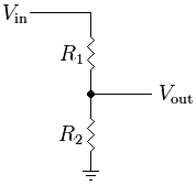
You can use a resistive divider to get the 5V. The laser module is 12V input power, so:

Resistive_divider.png


Connect Vin to the laser power source (12V), make R1 10Kohms, R2, 6.8Kohms, and then Vout is your 5V for the potentiometers.
 
You can use a resistive divider to get the 5V. The laser module is 12V input power, so:

Resistive_divider.png


Connect Vin to the laser power source (12V), make R1 10Kohms, R2, 6.8Kohms, and then Vout is your 5V for the potentiometers.

as members of this forum , i use this module as portable.
I use 2x26650 batteries so I use R1 10Kohms and R2 15Kohms

5.040V= 8,4*15000/10000+15000
:thanks:
 
If that is same as my W800 there are three fan outputs which I believe are 5volt. Only two fans uses so there is a vacant 5v output jack.

Double check...I did not measure but manufacturer says the fans are 5 VDC.


Back
Top