- Joined
- Dec 22, 2010
- Messages
- 227
- Points
- 18
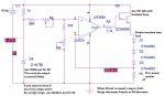
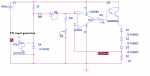
Ill try to find a schematic for an op-amp driver ") I know that I can set the max current with R4, but I wanted a dynamic solution that can be modded when swapping to different lasers without having to change resistor values etc. Thanks for your post.
I know that I can set the max current with R4, but I wanted a dynamic solution that can be modded when swapping to different lasers without having to change resistor values etc. Thanks for your post.
I know that I can set the max current with R4, but I wanted a dynamic solution that can be modded when swapping to different lasers without having to change resistor values etc. Thanks for your post.