- Joined
- Mar 30, 2013
- Messages
- 7
- Points
- 0
Hey guys,
I've bought a 8W 808nm c-mount laser diode and some protection goggles for a pretty cheap price, but i cannot find any driver suitable of outputting 8A at 2 volts as the datasheet of the diode says.
As i always wanted to build electric devices on my own i just made this little schematic of a constant current driver which should work if i remember my physics lesson correctly.
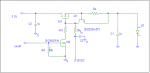
Ok, i tried to improve the driver according to your feedback, this is what came out.

Im still having the problem to decide which mosfet to use for pwm modulation, it has to be a logic level mosfet which is pretty fast.
I'm also curious how clean the output of the driver will be.
If i calculated correctly, the Transistor regulating the voltage has to have an amplification factor of 40 (200mA Base current and 8A output). As i want to feed it with a 3.3V power supply (2V output) i cant use a darlington transistor
Should i use 2 Resistors to get the reference voltage (as a PC power supply is already stabilized
Does anyone know a single AND gate IC?
Ohh, and because i failed with EAGLE again, R11 needs to be 0.0875 Ohms
I've bought a 8W 808nm c-mount laser diode and some protection goggles for a pretty cheap price, but i cannot find any driver suitable of outputting 8A at 2 volts as the datasheet of the diode says.
As i always wanted to build electric devices on my own i just made this little schematic of a constant current driver which should work if i remember my physics lesson correctly.
Ok, i tried to improve the driver according to your feedback, this is what came out.
Im still having the problem to decide which mosfet to use for pwm modulation, it has to be a logic level mosfet which is pretty fast.
I'm also curious how clean the output of the driver will be.
If i calculated correctly, the Transistor regulating the voltage has to have an amplification factor of 40 (200mA Base current and 8A output). As i want to feed it with a 3.3V power supply (2V output) i cant use a darlington transistor
Should i use 2 Resistors to get the reference voltage (as a PC power supply is already stabilized
Does anyone know a single AND gate IC?
Ohh, and because i failed with EAGLE again, R11 needs to be 0.0875 Ohms
Last edited:


")