Welcome to Laser Pointer Forums - discuss green laser pointers, blue laser pointers, and all types of lasers

LPF Donation via Stripe | LPF Donation - Other Methods

Links below open in new window

ArcticMyst Security by Avery

OPEN SOURCE: The "Heavy Load" - REALLY high current (10 Amp) test load

rhd

0
Joined
Dec 7, 2010
Messages
8,475
Points
0
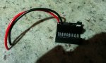
I wanted a higher current test load to try out some high current buck driver designs, so I made this:

attachment.php


Some of the neat features I decided to add:

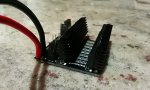
  • Ability to handle up to 10 Amps! (though at that current, even with the heatsinks, I'll have to stick to a short duty cycle)
  • Ability to swap the resistor inline (or not) with the circuit, via a jumper. This is useful if you just want to use an ammeter inline with the circuit, and don't care about measuring voltage drop across a resistor.
  • Can handle really thick gauge leads.
  • All-black PCB, all-black ICs, all-black heatsink. Okay.... this feature was purely aesthetic.
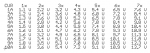
  • Includes a Voltage/Current table, printed on the board itself:

attachment.php


Voltage drops listed are for ammeter mode.
For resistor mode, add an additional 1V for each 1A of current.

It works surprisingly well, and the the current/voltage table is reasonably accurate, even at fairly high currents (voltage drop estimates on the table were usually within 5 to 10% of the actual drop).
 

Attachments

  • IMG_20140226_223125.jpg
    IMG_20140226_223125.jpg
    170.8 KB · Views: 288
  • Table.png
    Table.png
    28.5 KB · Views: 933
  • IMG_20140226_224503.jpg
    IMG_20140226_224503.jpg
    134 KB · Views: 943
Last edited:


Joined
Mar 29, 2013
Messages
1,221
Points
63
Re: The "Heavy Load" - REALLY high current (10 Amp) test load

Going the use this to set your drivers for the new generation 3.5w blue diodes yeah?

Good stuff! Looks nice! Which PCB manufacturer did you use?

:beer:
-Matt
 

rhd

0
Joined
Dec 7, 2010
Messages
8,475
Points
0
Re: The "Heavy Load" - REALLY high current (10 Amp) test load

Going the use this to set your drivers for the new generation 3.5w blue diodes yeah?

Good stuff! Looks nice! Which PCB manufacturer did you use?

:beer:
-Matt

SeeedStudio I believe - basically, once you get above 3 square inches, they're more economical than Oshpark.
 

rhd

0
Joined
Dec 7, 2010
Messages
8,475
Points
0
Re: The "Heavy Load" - REALLY high current (10 Amp) test load

Perhaps I should have posted this here instead. Anyone who wants to make this board is free to. I actually improved the design a bit, but never bothered ordering the improved version myself.

The improved version puts the resistor IC in line with the diodes physically, so that they're easier to heatsink (and there are now only 7 diodes instead of 8). It also staggers the diodes between rows, so that if you're only using 4 diodes, it uses 2 diodes in each row, instead of 4 diodes in one row and none in the other. This makes for better heat dissipation.

This is the diode used: Digikey
The voltage drop chart isn't just a guess, it's a calculated chart based on the voltage drop at various currents based on the graph in the datasheet for this specific diode.

Even though the board itself suggests using a 1 ohm resistor, I would strongly suggest moving to a 0.1 ohm resistor instead. It doesn't really make the conversion hard (just move a decimal place in your head), and it saves you from dropping 4V over the resistor when you're testing 4A, etc. That's a lot of voltage drop.

attachment.php


attachment.php
 

Attachments

  • High Current Test Load V08.zip
    6.6 KB · Views: 54

IWIRE

0
Joined
Dec 18, 2013
Messages
630
Points
0


That's a beautiful test load rhd. I'm going to install my heat sink tomorrow and give it a workout . Thanks for making these open source :beer:
 

rhd

0
Joined
Dec 7, 2010
Messages
8,475
Points
0
Glad you like it :)

I've actually been using mine up at 10A recently. It seemed overkill at the time I designed it, but now I'm really glad for the high current capabilities.
 

IWIRE

0
Joined
Dec 18, 2013
Messages
630
Points
0
Not only is it functional, it's a work of art ! It was fun to put together too. I think I'll order another board and build the new style too when I place my next board order. :)
 

rhd

0
Joined
Dec 7, 2010
Messages
8,475
Points
0
Not only is it functional, it's a work of art ! It was fun to put together too. I think I'll order another board and build the new style too when I place my next board order. :)

If you decide to do that, let me know.

I'll place an order with iTead and it will cost us the same for 10x from them, than 1x from oshpark.

Edit: plus we get the nice black, instead of oshparks purple!
 
Last edited:
Joined
Jul 4, 2012
Messages
2,834
Points
63
I would love to make one of these, so I would be in for a small group order. Is there any way you could change it so we could put screw terminals for the input? Like these:
im120811007_2.jpg


Or maybe those would fit anyway?
 
Last edited:

rhd

0
Joined
Dec 7, 2010
Messages
8,475
Points
0
I would love to make one of these, so I would be in for a small group order. Is there any way you could change it so we could put screw terminals for the input? Like these:
im120811007_2.jpg


Or maybe those would fit anyway?

Yep, no problem. I'll give it a day or so to see if any other requests come in (though I'm not really asking for anyone to go crazy here please) and I'll revise the board.

Edit: Think you could find the Digikey part for me though?

It would be kind of cool if we could find some sort of spring loaded grip for the DMM test probes. Something that would be really quick to pull in and out of.
 
Last edited:
Joined
Jul 4, 2012
Messages
2,834
Points
63
Yea I agree, I was going to say something but I wasnt sure if such a thing existed my test load right now has two alligator clips on each side of the resistor thay I slide the probes of my dmm into...they fall out a lot, and the clips can spin around and short, so I have to be careful.

Ill find the digikey page for those screw terminals, and/or spring terminals

edit: screw terminal. Keeping with the black theme, of course. I know what you are talking about with the spring terminal, but they are proving hard to find. Just not quite sure what to search. Ive been trying "spring terminal", "spring wire terminal," etc etc, to no avail.

second edit: Eh, this is closest I could find: link. Looks kinda derpy, not what I had in mind.

THIRD edit: Oh hey, look at these. Quite a bit bigger and more expensive, but that kinda thing would work the best. Maybe there is a mini version of them somewhere? Its late and im tired, so I will look more tomorrow (well, later today at this point)
 
Last edited:

rhd

0
Joined
Dec 7, 2010
Messages
8,475
Points
0
I actually don't mind these too much:
Invalid Request

But I'm also somewhat concerned that the contact points will be too close together to attached two DMM probes side by side. That's why I sort of like this:
Invalid Request

...except for the color.
 

IWIRE

0
Joined
Dec 18, 2013
Messages
630
Points
0
If you decide to do that, let me know.

I'll place an order with iTead and it will cost us the same for 10x from them, than 1x from oshpark.

Edit: plus we get the nice black, instead of oshparks purple!

Thanks ! Count me in for 4 boards. I want another for me, one for a member that's helping me with a project I'm building, and a couple spares for when I smoke test one :)
If you change the board I'm cool with whatever you come up with.
Personally I like it the way it is, if I was going to change anything it would be to make it slightly larger for heat sinking. But I'm a power junkie, not everyone is.

Thanks for all you do rhd :beer:
 

rhd

0
Joined
Dec 7, 2010
Messages
8,475
Points
0
The board was changed a few times following the ones I had fabbed (but I never refabbed new ones). The primary meaningful changes are:

1) A decrease from 8 to 7 diodes so that the resistor could be placed in line (and thus heatsinked with) the diodes.

2) Staggering diodes between the two rows, rather than lining them sequentially in a row. This means that if you're running 4 diodes, you get 2 from each heatsink, rather than getting all 4 from one heatsink, and none from the other. IE, better heat dissipation when using less than all of the diodes (which is probably true for 95% of the use cases).

EDIT: But I would love to add terminals, if we can find and agree on the right ones. That's a no-brainer in my mind.

Basically, it's about $20 to get 10x of the boards, in that nice BLACK color, fabbed from iTead. Compare that to $20 for 3x from Oshpark in the (somewhat tiresome) PURPLE color. So iTead is the clear winner here. If I can have them shipped to someone in the US, instead of to me in Canada, I'm cool with you guys doing whatever you want with 9x of them, as long as the recipient will mail me 1x :) If others want to contribute a few bucks, that's cool. But $20 isn't exactly a piggy bank breaker :)
 
Last edited:
Joined
Jul 4, 2012
Messages
2,834
Points
63
I say screw terminals for the input, and those spring terminals for the probes, and call it good.

Heh, the way you talk about the purple boards makes it seem like you think they are absolute scum.. "And we can get black boards, not those disgusting, worthless... purple boards..." :p

edit: do you have a part list for these? also, where did you get the heatsink?
edit^2: if they are that cheap I will probably take 2-3. if IWIRE wants 4, you and I could each get 3, RHD, if you want. The parts are cheap enough i could put them together and sell them for the cost of said parts and shipping, for anyone that needs a good test load.
 
Last edited:


Top