Welcome to Laser Pointer Forums - discuss green laser pointers, blue laser pointers, and all types of lasers

Buy Site Supporter Role (remove some ads) | LPF Donations

Links below open in new window

FrozenGate by Avery

Has anyone had experience making a (negative) regulating version of the DDL ?

rhd

0
Joined
Dec 7, 2010
Messages
8,469
Points
0
Subject line says it all -

I'm aware of the LM337, and that's about it for negative regulating alternatives to the ICs we use for our DDL circuits- at least as far as I'm aware.

Has anyone done a DDL driver build with this, or another neg regulating IC?


Why would you need to use a negative Regulator...
The are to be used for the negative rail in +/- split
power supplies...


Jerry
 
I'm interested in this as well. I have a case positive 635 diode that needs to find its way into one of my empty hosts soon.
 
I remember a post about this but I cant find it. Basically you don't need a Negative regulator, because its still a positive supply. The only difference is that positive is common, IIRC you can do something like this with a positive regulator(like the LM1117):

5558-pos-common.png


***I have not tested this ... try at your own risk***
 
Last edited:
It can't electrically "see" where the load is. Its only task in life is to keep 1.25V across that sense resistor.

I just tried it (with an LED) and it regulates the same.
 
hmm. interesting idea jib. Shouldn't be too hard to test using a dummy load and an LM317. Time to get out my breadboard and do some testing. I'll report back later.
 
hmm. interesting idea jib. Shouldn't be too hard to test using a dummy load and an LM317. Time to get out my breadboard and do some testing. I'll report back later.

I'll be anxious to hear back. If it works for you, I may just do a high powered IR build tonight :)
 
Uh, guys, do you not understand how voltage potentials or diodes work? Just because your diode is case positive doesn't mean the diode itself is. There are no negative voltage diodes. Current always flows from positive to negative (well, at least using the nomenclature). Even with Zener diodes, it is merely acting like a normal diode should the voltage swing the other direction too; so it's not really "negative" voltage with respect to that diode.

You don't need a negative voltage regulator unless you really do need negative voltage. Unless you're connecting up your laser diodes in some fashion where you need to share a ground among different lasers with different case potentials, you can just as easily switch the leads on your LM317's output. To generalize: just connect the laser up according to the diode diagram in the datasheet. Green lasers, after all, just power a IR laser, and the only thing that is different is that it is case-positive. The regulator, however, doesn't change.

If you're still hell-bent on using a negative regulator, you can just copy the current regulator in the datasheet. Still, you're not gaining anything by it, and it's probably a more expensive and exotic part.

I think most of us understood what we were looking for - but perhaps used the wrong terminology.

When I suggested that I needed a negative regulating IC, what I was really trying to say was:
"I want to regulate the (-) and keep the (+) continuous, instead of vice versa (as is the case with normal DDL circuits)"

Now it may be the case that we really can just flip the +/- as in Jib's circuit diagram. However, I'm having trouble seeing why this would just be a natural "given" so to speak. It strikes me that in Jib's proposed circuit here, current is flowing through the IC in a direction opposite to how it would in a time-tested DDL circuit.
- That may still work, and I hope it does. But I don't understand how we can just assume that this IC will allow current to flow in either direction. It seems like this might be dependant on the internals of how the IC works, no?
 
Last edited:
I'll be anxious to hear back. If it works for you, I may just do a high powered IR build tonight :)

It works. Whether the lm317 is before or after the load doesn't seem to matter. See my above post.
 
Last edited:
The current doesnt flow in a different direction, the regulation just takes place on the return path to the cell instead of the supply side.

So instead of this:

v+ ===> reg ===> diode ===> v-

You are doing this:

v+ ===> diode ===> reg ===> v-

The end result should be the same.


I think most of us understood what we were looking for - but perhaps used the wrong terminology.

When I suggested that I needed a negative regulating IC, what I was really trying to say was:
"I want to regulate the (-) and keep the (+) continuous, instead of vice versa (as is the case with normal DDL circuits)"

Now it may be the case that we really can just flip the +/- as in Jib's circuit diagram. However, I'm having trouble seeing why this would just be a natural "given" so to speak. It strikes me that in Jib's proposed circuit here, current is flowing through the IC in a direction opposite to how it would in a time-tested DDL circuit.
- That may still work, and I hope it does. But I don't understand how we can just assume that this IC will allow current to flow in either direction. It seems like this might be dependant on the internals of how the IC works, no?

The only assumptions you should make are what the IC is designed to do. All the magic that occurs inside it is doesn't matter as long as you're working within its specs and it's doing what you want. In the case of Jib's circuit, the idea behind it is that current out is equal to current in, so you can hook the input of the LM317 to the laser diode to make it a current sink.

You should really only use a negative voltage regulator if your power input literally can't be made independent from the ground of another circuit. Otherwise, it is better to use a simple positive regulator: they have better ripple rejection, are easier to find, and are usually cheaper. There is literally no reason you should use a negative voltage regulator unless you're hooking it up to some transformer windings where you can't separate the center tap.

Another thing too, are you just looking voltage regulate, as in just regulate a voltage differential, or do you want to do some modulation of some sort? If the latter, you should use a transistor current sink to regulate and change current. Otherwise, the positive voltage regulator is all you need if you just need a voltage differential regulated.
 
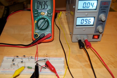
Ok now that I've watched some explosions here's an update.

Well that was easy. My testing shows jib is correct. I started with an LM317 with 3x10ohm resisotrs giving me a steady 43.5mv across my test load. To test jib's theory I basically recreated his diagram substituting the laser diode with my test load. I attached V+ from my bench supply to the first diode in my test load then connected the 1ohm resistor to Vin on the LM317. Vout was connected to ground. The result was a steady 43.5mv across the resistor. Looks like this will work nicely for case positive diodes. I don't have any other regulators around but I don't see any reason why they wouldn't work like this as well. As always test your circuit first before attaching your diode.

As they say a picture is worth a thousand words...


2011-07-04_09-14-43pm by ltkernelpanic, on Flickr

Full size available on Flickr.
 
The current doesnt flow in a different direction, the regulation just takes place on the return path to the cell instead of the supply side.

So instead of this:
v+ ===> reg ===> diode ===> v-

You are doing this:
v+ ===> diode ===> reg ===> v-

The end result should be the same.

I'm with you 100%. I don't know how I didn't see that before ;)
 
So took the plunge tonight and actually built a laser using the design on my breadboard pictured above. The driver puts out a steady 71ma and everything works great but when I LPM'd it my 20mw 635nm diode was only putting out 5mw instead of the 20 it's rated at when driven at 70ma. I doubt it's my Alpha that's off that much either. The only thing I can think of is the 1N4001 diode I put between LD- and Vin on the LM317 is doing something funky. Before I tear it apart and start desoldering things would that potentially cause what I'm seeing? I can move the diode to between the LM317's Vout and Batt- but it'll be harder to fit in the host there.


edit: the diode is there to stop a reverse polarity from cooking the diode. Although with the load before the regulator would the LM317 even conduct backwards? Maybe the diode isn't needed at all.

edit #2: After thinking about it for a minute it has to be. The diode only uses 2.3v so with the diode in series only ~1.6v is getting to the LM317 causing it to drop out pf regulation. Time to get out my DMM and bench supply again and see what I find.


edit #3: Well I was wrong about what I said above. I couldn't measure the current with my DMM (not sure where to probe actually) but my bench supply showed it was pulling a steady .07A or 70ma. With my bench supply set to 12.5v I also measured 10.2v (mine the 2.3v Vf of the LD) between Vout and Batt- so it's not dropping out of regulation. That leaves one thing -- the diode. Looks like something potentially shorted or I just got a dud. since modwerx sells these same diodes now I may pick up another one and run it in a "standard" linear diver setup on my breadboard and test the diode at the rated 70ma and see if I get 20mw.
 
Last edited:


Back
Top