Welcome to Laser Pointer Forums - discuss green laser pointers, blue laser pointers, and all types of lasers

LPF Donation via Stripe | LPF Donation - Other Methods

Links below open in new window

ArcticMyst Security by Avery

Has anyone had experience making a (negative) regulating version of the DDL ?

chefla

0
Joined
Mar 24, 2011
Messages
169
Points
18
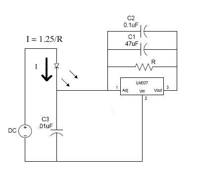
You guys might want to try the LT3015 from Linear. It is a true negative regulator and good for up to 1.5 Amps.


midias

0
Joined
Mar 14, 2010
Messages
631
Points
0
LM337 Neg regulator built it used it and currently using it for my 635nm pen

lowside.jpg


DSC00674.jpg


DSC00673.jpg
 

rhd

0
Joined
Dec 7, 2010
Messages
8,475
Points
0
So instead of this:

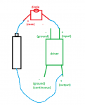
v+ ===> reg ===> diode ===> v-

You are doing this:

v+ ===> diode ===> reg ===> v-

The end result should be the same.

Something has been driving me nuts here, and it all has to do with where we get the (-) feed for the driver.

The only thing that makes sense in my head, is from the battery (+). But that doesn't *actually* make sense in my head.

Excuse the awfulness of this drawing:
attachment.php
 

Attachments

  • huh.png
    huh.png
    13.5 KB · Views: 409

jib77

0
Joined
Jun 19, 2010
Messages
718
Points
0
The driver's negative becomes the common positive plane, it should be tied to the battery positive or case.

5943-neg-driver.png
 

rhd

0
Joined
Dec 7, 2010
Messages
8,475
Points
0
jib77:966212 said:
The driver's negative becomes the common positive plane, it should be tied to the battery positive or case.

5943-neg-driver.png

I guess my gut was correct. It's just hard to get my head around the ground coming from battery positive. It makes sense though.

Thanks Jib
 
Joined
Oct 24, 2009
Messages
2,555
Points
48
if you want a negative regulating driver capable of 2a and softstart send me a msg.
 
Joined
Jan 14, 2011
Messages
3,816
Points
63
Yeah - I actually have a build using one of these with the IR diode you sent me, rhd. Why didn't you just ask for how I used the driver? XD
 
Joined
Mar 29, 2011
Messages
1,056
Points
48
can anyone tell me if this is possible with a switching driver?

AX2002 IC for example???

I am trying to use that with a case positive diode? :thinking::thinking:
 

midias

0
Joined
Mar 14, 2010
Messages
631
Points
0
can anyone tell me if this is possible with a switching driver?

AX2002 IC for example???

I am trying to use that with a case positive diode? :thinking::thinking:

Well buck boost are not going to let you do it exactly the same if you have a data sheet I could probably help you more.
 
Joined
Mar 29, 2011
Messages
1,056
Points
48
Ok so it's 3:30 am here now in Bulgaria... and I am not sleeping :D

I decided to test this with LM1117 and it kinda works but not exactly!

So I made my own PCB according to the diagram I double and triple checked
everything :

B+ to case
B- to Adj pin and cap's negative
Vin to diode's negative and cap's negative

I set the current to nearly 380mA. ..~370mA something
I connected the test load, connected the adjustable power supply,
pushed the button and now comes the funny stuff :D

when I was cranking up the voltage from 0V to 6V i got a steady current
going up! Good for now.. at 6V I got to the 370mA.. So I started cheering ..
then I turned the voltage up and WHOA?! the current suddenly dropped to
250mA and stayed there no matter how many volts I fed it with....

when I returned to 6V input I got my 370mA current again...

so I decided to see how does it behave on my 150mW IR diode..
it's maximum current is 380mA.. and I have set it to almost there..

now I stared from 0V again and when I reached 4.7V the current
was 370mA so I decided to stop cranking the voltage up and see what
happens next..

at some moments later what I saw was that the current was slowly
starting to rise due to heat... the hotter the diode and driver got the
more current was going in.. from 370mA it went to 380mA and I turned it off..
don't want to kill my diode :D

because if had crossed the border of regulation... I think it's not regulating
properly when connected after the diode... I don't know how it turned out
for you guys but for me it didn't work.. maybe LM317 behaves differently in
this manner but my LM1117 doesn't... :gun::cryyy:

well I just wanted to share that with you ... if you have any suggestions or thoughts pls share :)

I am going to get some sleep now ... it's almost 4am ..... goodnight :can:

p.S. I guess that's why there are negative rail regulators and positive rail regulators and not just
ONE of them if it worked both ways don't you think?? :D:D
I think this was doomed from the beginning ...
 
Last edited:
Joined
Feb 7, 2012
Messages
977
Points
0
Sorry to jump in I'm a dweeb at electronix.. I wired a few arduino's but nothing special.. I need an RHD crash course in electronics... and from what I have read I'm there... Thx RHD.
 
Last edited:


Top