Welcome to Laser Pointer Forums - discuss green laser pointers, blue laser pointers, and all types of lasers

LPF Donation via Stripe | LPF Donation - Other Methods

Links below open in new window

ArcticMyst Security by Avery

Got some ?s about the Groove2 drive.

Joined
Nov 28, 2010
Messages
9
Points
0
I ordered a groove2 drive and have learned that it is the least efficient of all the dr. lava drives. So I have decided to turn it into my diode tester supply to make sure my diodes are working properly when I recieve them in the mail. What would be the easiest ways to set it up so it can test all diodes. I will just be using a standard 9 VDC powersupply as my input voltage, and will have the diode in its own heatsink with the driver attatched to the side of one of the fins of my heatsink. I would like to know the proper wiring methods for setting it up so it runs any diode I hook up, but mostly reds and blu-ray diodes. If anybody needs me to do a layout of how I want it to look when done then that is no problem just give me a little bit. Sorry if I confuse anyone with this post I tried to explain what I am doing the best way I can without pics. I'm still a noob so sorry if this is an easy thing to answer. i just couldn't find very much info on the forums.


Thanks,
Casey


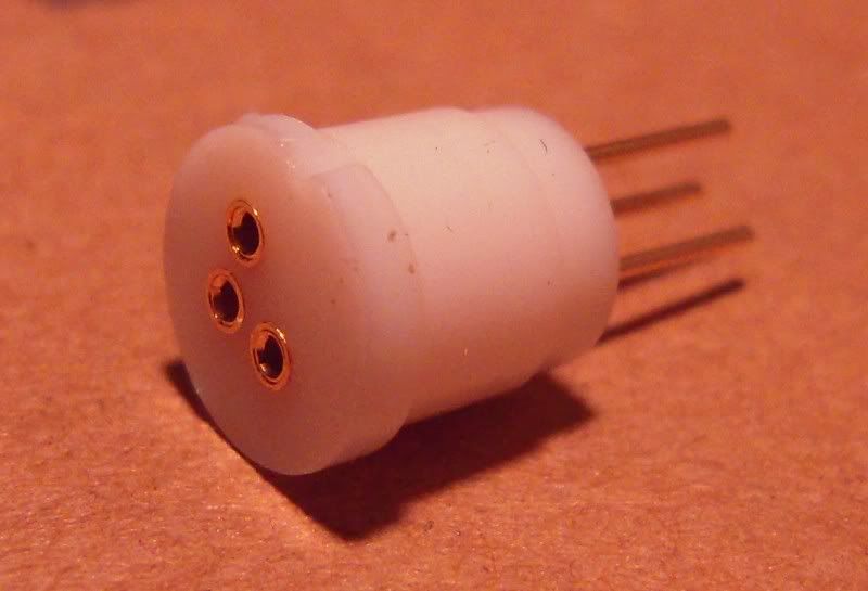
EDIT: The pic below is similar to how I will have it laid out.
 

Attachments

  • Groove2 Diode Tester Supply.bmp
    769.7 KB · Views: 191
Last edited:


Kevlar

0
Joined
Apr 26, 2010
Messages
1,353
Points
48
The plans you have seem like they would be ok. If you're using this as testing bed for your diodes then I assume you won't be powering them too long, just long enough to be sure they are not DOA. So with heatsinking the driver I don't really see heat being an issue. This came to mind first because the Groove2 being a linear current regulator it needs 1.2V for the driver + the diode voltage. So a red diode needs ~3V plus 1.2V for the driver = 4.2V. The leftover 4.8V is going to be dissipated as heat from the driver.

The only thing I would add would be a "diode socket" like this:

DSCN2572-b.jpg


IMO this would make it easy to switch diodes.
 
Joined
Nov 28, 2010
Messages
9
Points
0
Yeah I thought about the diode sockets for easy swap out. My question is how will the blu-ray diode get wired to the driver if there is no case negative? Just a typical connection like +in to driver/-in to driver and +out to diode/-out to diode, and do not use the case pin?
 

Kevlar

0
Joined
Apr 26, 2010
Messages
1,353
Points
48
Just a typical connection like +in to driver/-in to driver and +out to diode/-out to diode, and do not use the case pin?

That is how I would do it. But since the pinouts are different on red diodes and 405nm/445nm diodes, you would have to wire in a switch between the driver and the diode socket.


Top