Toke
0
- Joined
- Jul 25, 2010
- Messages
- 1,099
- Points
- 0
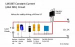
I would like to state the obvious in case anyone overlooked it on midias drawings.
The pinout of the LM317 is swapped around between the schematics and the actual component.
It is rather annoying and have in corporation with too much beer cost me two LOC's some months back.
The pinout of the LM317 is swapped around between the schematics and the actual component.
It is rather annoying and have in corporation with too much beer cost me two LOC's some months back.