Welcome to Laser Pointer Forums - discuss green laser pointers, blue laser pointers, and all types of lasers

LPF Donation via Stripe | LPF Donation - Other Methods

Links below open in new window

ArcticMyst Security by Avery

God i hate drivers. Can i do this instead?

Joined
Feb 5, 2008
Messages
6,252
Points
83
Going through the thread, nobody noticed the problem that he's using nothing but a resistor?

Lascannon. Sorry for your hate of drivers, but that's approximately equal to hating the engine inside your car. It ain't running without it!

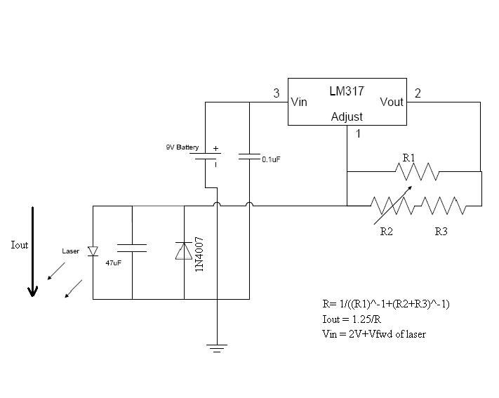
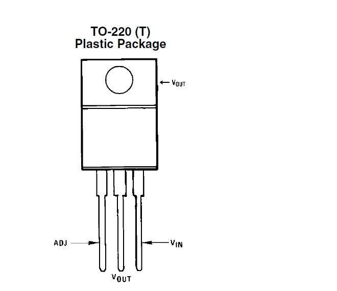
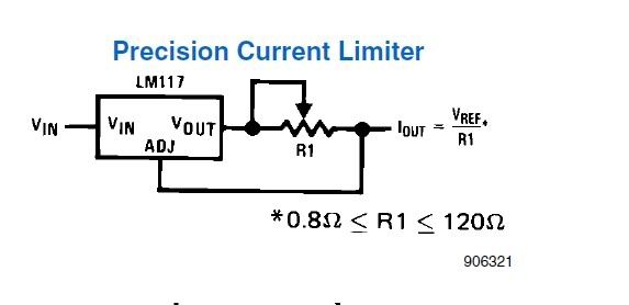
LM317 circuit is much easier to construct than you think. You do not need a trimmer, two resistors, rectifier diode and specific capacitor.

Any capacitor on output will do. One resistor is enough to set the current to the LM317 (between it's two Vref pins). That's it. Three components.

English has worse spelling than any other language

You haven't tried Croatian, have you?

BTW, when referring to yourself, "I" is a capital letter. Always, no exceptions.


Joined
Feb 17, 2011
Messages
167
Points
0
Eudaimonium. Thank you so much. That is exactly the kind of reply I have been looking for all week. I am incredibly greatfull. So, where do I need to put the capacitor? Im rather confused about them... So do i just connect the possitive lead on the cap to the negative terminal on the battery(batery?) and the possitive lead to the chip, or do I...

Anyway you get the confusion im sure, is there any chance you could direct me to a schematic?

As for the language thing, maybe I will learn croatian next :D

Thank you so much
Liam.
 
Joined
Feb 5, 2008
Messages
6,252
Points
83
Eudaimonium. Thank you so much. That is exactly the kind of reply I have been looking for all week. I am incredibly greatfull. So, where do I need to put the capacitor? Im rather confused about them... So do i just connect the possitive lead on the cap to the negative terminal on the battery(batery?) and the possitive lead to the chip, or do I...

Anyway you get the confusion im sure, is there any chance you could direct me to a schematic?

As for the language thing, maybe I will learn croatian next :D

Thank you so much
Liam.
I have a schematic somewhere...

ddl.jpg


Ah there we go. I need to start sorting my stuff over at Photobucket, man :D

Anyhow, capacitor goes parralel to diode.

You see, capacitors act like this:

When they are empty, they act like piece of wire, a conductor. So, you engage the circuit, apply power. LM317 gets the voltage and starts regulating the current and provide voltage at output. However, until it properly starts working, there are so called "ON spikes" happening. Voltage surges that happen before LM317 pulls itself together.

This is where capacitor is needed. They begin empty in a circuit. Initial microseconds of circuit operations, they devour the voltage and current applied. As they get full, they start to act like open switch - they do not conduct current, as if they are not even there. So the laser diode is left with good current.

This is simplified version of actual happenings, but you'll get the idea.

About the resistor, it servers as current setter. You see, LM chip gives a constant voltage between it's two pins, OUT and ADJ. A resistance between those pins in turn sets the output current, given that the voltage is fixed, according to Ohm's law:
Voltage = Current / Resistance.

Turning that formula around:
Resistance = Voltage / Current,

where Voltage is 1.25 V provided by LM317, and current is the one you need for powering your laser diode.

So let's say you need 100mA = You need 12.5 ohms.

Going with 3.3 ohms gives you around 380mA, perfect for powering red diodes.

And about learning Croatian... hah. You'll give up before you get the basics. People say language spoken at Iceland is most difficult to learn. That's just because they can't find Croatia on the damned map. :D
 

anselm

0
Joined
Nov 22, 2010
Messages
2,448
Points
0
So do i just connect the possitive lead on the cap to the negative terminal on the battery(batery?) and the possitive lead to the chip, or do I...
No, you're trying to wire the capacitor in series, which would block all
current from flowing.
You'll want to wire the cap in parallel instead.
direct me to a schematic?
What's wrong with the one in the link I gave you?:thinking:
You can just leave out the diode and the potentiometer if you want it as simple as possible.

English does have funny spelling:
Ghoti: an animal that lives in the water and breathes through gills.:D
Gh as in tough,
o as in women,
ti as in -tion.
Gh-o-ti.:D:D
 

Benm

0
Joined
Aug 16, 2007
Messages
7,896
Points
113
English has worse spelling than any other language i know other than maybe french. :D

English transcription is really afwul. It is one of the few languages where it is semi-impossible to figure out how to pronounce written text without having heard the words spoken aloud before.

Sometimes this yields funny results: I've met some people that learned english in writing, but never made any verbal conversation. Its quite a surprise to meet someone that is fluent in writing, but can't pronounce a setence at all.
 
Joined
Feb 17, 2011
Messages
167
Points
0
Anselm: It turns out your schematic would have worked, I just wante to make sure everyone here was on the same "page". I now understand what you mean (meen?) about the capacitor. Thank you.

Eudaimonium: Thank you so much for taking the time to write out a full explanation for a newby. It was extremely helpfull. Between you and Aselm, I now have all the information needed to make this work.

Thank you all. I will now start construction. Il let you know how it goes in a minute :D

Thanks alot,
Liam.

Edit: So my iron is powering up, and it occured to me that i have no idea what to run it off of...
I dont have any spetial batteries available, although I can order some. How many volts should I be inputing?

Edit 2: Ok, I have everything but my a 3.3 ohm resistor. I dont have anything smaller then 10 ohm here, so il have to run to radioshack tonight. How small do they go? Is it possible to buy a 0.3 or 0.1 ohm?

Thanks,
Liam.
 
Last edited:
Joined
Feb 5, 2008
Messages
6,252
Points
83
No problems man, it's what I mostly do around here (besides showing off with some of my modest builds but that's marginal).

If there are any questions that you don't want to raise a thread about, you can simply PM me and ask me. I usually help people out.
 

midias

0
Joined
Mar 14, 2010
Messages
631
Points
0
here is my last red LM317 build schematic. I designed to to make sure I could never over current but it would also be adjustable. Schematic and pics radio shack should have all the items. I use a 9V but you can also use 2 li-ion 3.7 cells

CClm317.jpg


DSC00622.jpg


DSC00621.jpg


Adjustment pot

DSC00619.jpg
 
Joined
Feb 5, 2008
Messages
6,252
Points
83
Midias... ehhh :D

Why make it simply when it can be so damn complicated? It's the man's first build!

Let him see some coherent light before showing him a schematic 3x more complicated and basically does the same thing.
 

midias

0
Joined
Mar 14, 2010
Messages
631
Points
0
Midias... ehhh :D

Why make it simply when it can be so damn complicated? It's the man's first build!

Let him see some coherent light before showing him a schematic 3x more complicated and basically does the same thing.

Whats wrong with a little more complicated. Personally I like a challenge.
 
Joined
Feb 5, 2008
Messages
6,252
Points
83
Whats wrong with a little more complicated. Personally I like a challenge.
Not everybody does.

What's wrong with complicated is that it's complicated, and does not have to be.

What makes your 10 component schematic better than 3 component one, being worth of building, by somebody who's never built an electronic circuit before?
 

midias

0
Joined
Mar 14, 2010
Messages
631
Points
0
Not everybody does.

What's wrong with complicated is that it's complicated, and does not have to be.

What makes your 10 component schematic better than 3 component one, being worth of building, by somebody who's never built an electronic circuit before?

What makes it better for a new builder is it is safer for the diode. It has reverse polarity protection and max current limiting while still allowing the person to play with the current settings of their diode vs a single pot. Yes it is more complicated but it is also more rewarding.

I was not telling him he had to go that way I was just throwing up a couple pics with some strip board and some radio shack components to show how easy and clean it can be I am not sure why you are all bent out of shape. I never said do this all I said was this is what I did and here are some pics.
 
Joined
Feb 17, 2011
Messages
167
Points
0
Ok, so im now kind of annoyed(anoyed?). So i ordered some 3.7v lithium ion rechargable AA baterys, and they arived today, so i wired up the laser as follows: Positive power cable from batery case to righthand pin on the lm317, 1 ohm and 2.2 ohm resistors in series between central and right hand pin, then from left pin of lm317 to possitive end of a cap and the laser diode in paralel, then back to the bateries. I have 7.2v in, which should be perfect, i have 3.2 ohms of resistence, the cap is in paralel so it shouldnt do anything enless it spikes... What have i dont wrong? btw, theres also a switch in there somewhere.
 

anselm

0
Joined
Nov 22, 2010
Messages
2,448
Points
0
1 ohm and 2.2 ohm resistors in series between central and right hand pin,
That's your mistake, those resistors are supposed to be between the CENTRAL pin and the
LEFT hand and pin.;)
How is the negative path of your current wired exactly?
 

midias

0
Joined
Mar 14, 2010
Messages
631
Points
0
Ok, so im now kind of annoyed(anoyed?). So i ordered some 3.7v lithium ion rechargable AA baterys, and they arived today, so i wired up the laser as follows: Positive power cable from batery case to righthand pin on the lm317, 1 ohm and 2.2 ohm resistors in series between central and right hand pin, then from left pin of lm317 to possitive end of a cap and the laser diode in paralel, then back to the bateries. I have 7.2v in, which should be perfect, i have 3.2 ohms of resistence, the cap is in paralel so it shouldnt do anything enless it spikes... What have i dont wrong? btw, theres also a switch in there somewhere.


That sounds wrong resistance should be between pin 1 and 2 so left and center. Double check here are some pics

to220.jpg


NewBitmapImage.jpg


Top