Welcome to Laser Pointer Forums - discuss green laser pointers, blue laser pointers, and all types of lasers

LPF Donation via Stripe | LPF Donation - Other Methods

Links below open in new window

ArcticMyst Security by Avery

FREE DIY open source BOOST driver!!! Tested & working!!

benmwv

0
Joined
Sep 10, 2010
Messages
1,380
Points
48
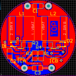
Jerry is absolutely right. As long as the PCB layout differs, it can be sold freely by anyone. Also, there is no IP in the use of the mosfet as a protection device. That is nothing new. National owns the IP for the remainder of the circuit.

I'm not trying to legally control anybody here. If somebody really desires to sell the circuit without permission there is nothing I can do to stop them.

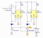
I never claimed to have pioneered the use of a mosfet as a protection device. As far as I know though I am the first to put it in a circuit with an lm3410. National does not own a circuit I made just because part of it was taken from their datasheet. But that doesn't even matter because the disclaimer wasn't directed at the schematic. If you want to take my schematic and base a circuit board design from it go ahead.

Also, by your logic there is no part of that circuit that national owns except for their IC sitting there with nothing connected to it considering that the use of an inductor to boost voltage is not new, the use of capacitors to smooth ripple isn't new, the use of resistors to sense current is not new, etc.

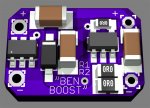
Is it not enough that we try to help the community by posting cheap boost driver designs for everyone to use, but we should also provide for everyone to make a profit off of it without giving a little back? I spent a good deal of money making and perfecting this design for the community, excuse me for wanting to gain some of it back!


Joined
Jan 2, 2009
Messages
11,800
Points
0
I think we all need to step back a second.

We have a great thing here, why bicker over something given freely. All it will do is discourage anyone in the future from freely sharing a great find.

Its Ben;s show. All he did was ask that people to contact him before selling. So what? They put in the time, and work, then they gave it away freely. If they were going to start charging for it, and DEMANDED no one steal it, its debatable. But its not, so why all the huff?
 
Joined
Jan 23, 2012
Messages
201
Points
0
Also, by your logic there is no part of that circuit that national owns except for their IC sitting there with nothing connected to it considering that the use of an inductor to boost voltage is not new, the use of capacitors to smooth ripple isn't new, the use of resistors to sense current is not new, etc.

Im not mad at you for trying to benefit a little!!

However, I do think you may be wrong about the above statement. If the external components are connected to the IC in the same manner as outlined in the datasheet, then it very well could be Nationals IP, regardless of their value. Obviously, under normal circumstances National would have no interest in preventing people from using their circuit, UNLESS, those people were claiming it to be their own.

The external components play a major part in the way the IC functions and National has probably spent just as much time developing the external circuit as they have the IC itself to ensure proper operation of the device in its entirety. Bottom line............Its Nationals circuit!!!
 
Joined
Nov 18, 2011
Messages
5
Points
0
Hi All,

First, thanks to sharing your project, I do the same with this adaptation.

I have personally tested other solution, but without success (TPS630xx), to hard to soldering.

I read, it's possible to use in parallel, i have modify your schematic for one PCB with 2 drivers. If i understand the schematic, in // is more simple:
attachment.php


I have removed the FET, because i can check the polarity before insert the battery. I stack the capacitor (22uF in 805 format and 16V, not exist !), the inductor is more height of 2 stack capacitor. The // the R1 et R2 is the for 2 LM, the LED current is the same, just needed lower value like 2 x 0R1.

In this way i have create small PCB in round of 25mm diameter:
attachment.php


I expected the manufacture of PCBs to test the idea. I'll let you know in 10 days.

Thanks
Olivier
 

Attachments

  • dual_sch.png
    dual_sch.png
    22.4 KB · Views: 1,587
  • dual_pcb.png
    dual_pcb.png
    118.5 KB · Views: 1,335

benmwv

0
Joined
Sep 10, 2010
Messages
1,380
Points
48
Im not mad at you for trying to benefit a little!!

However, I do think you may be wrong about the above statement. If the external components are connected to the IC in the same manner as outlined in the datasheet, then it very well could be Nationals IP, regardless of their value. Obviously, under normal circumstances National would have no interest in preventing people from using their circuit, UNLESS, those people were claiming it to be their own.

The external components play a major part in the way the IC functions and National has probably spent just as much time developing the external circuit as they have the IC itself to ensure proper operation of the device in its entirety. Bottom line............Its Nationals circuit!!!

I was just following the logical progression of what you said.

I completely agree that it it based off of nationals circuit, and the main part of the circuit was taken right from the datasheet. I am not pretending that I came up with the entire thing on my own. What I don't agree with is saying that the schematic as it appears in the first post is owned by national or is their intellectual property just because part of it was designed by them. Now can we let this rest?


Oliverg:

Nice board. We have a paralleled version also. One concern we had was that we would probably need to use shielded inductors to keep them from interacting with eachother since they are so close together.

I don't think two 0.1 ohm resistors will work. You don't have to individually set them both to the desired current, they will share sense resistors. Using two 0.1ohms would get you 3.8A instead of the 1.9A I assume you were going for. For 1.8A, you should use something like a .2 and a .22 ohm, use two 0.2 ohm for 1.9A. Also, here is the part number for a 22uf 0805 16v capacitor on digikey: 445-6797-1-ND ;)
 

rhd

0
Joined
Dec 7, 2010
Messages
8,475
Points
0
Im not mad at you for trying to benefit a little!!

However, I do think you may be wrong about the above statement. If the external components are connected to the IC in the same manner as outlined in the datasheet, then it very well could be Nationals IP, regardless of their value. Obviously, under normal circumstances National would have no interest in preventing people from using their circuit, UNLESS, those people were claiming it to be their own.

The external components play a major part in the way the IC functions and National has probably spent just as much time developing the external circuit as they have the IC itself to ensure proper operation of the device in its entirety. Bottom line............Its Nationals circuit!!!

It's funny to me that we wandered down this conversational road, since this, of all things on LPF, is the one creation where the creators were pretty explicitly NOT trying to personally benefit from it. But since we broached the subject, I think it's probably worth saying that NOBODY (including National) could likely have any IP in this circuit.

First off, you wouldn't have Copyright in a circuit. A circuit is knowledge, it's an idea. That's not something you can Copyright. You could have copyright over the actual artistic representation of the circuit in your datasheet (and National probably does), but someone could just illustrate the same circuit, and voila, they're probably safe.

So you'd be looking at Patent, but you're kind of screwed there too. For one, the circuit isn't "novel". If that circuit has been publicly disclosed elsewhere (and it has been) before hand, then it's not novel. This means no dice for the circuit designer since National disclosed the circuit in their datasheet. It also means no dice for National if they wanted to seek patent now, since they themselves released the circuit to the public many years back. Even if they hadn't, I'm very certain that someone, somewhere, would have. These are relatively speaking common circuits that I think you'll find have been floating around for a long time.

Further, the MOSFET mod, if it's been disclosed somewhere attached to a boost driver like this, is not novel. And even if the MOSFET mod wasn't disclosed on a boost driver exactly like this, but was disclosed *somewhere* as polarity protection, then its use on this circuit would be "obvious", and we're thus out of luck again. To be patentable, and invention needs to be non-obvious.

Long story short, I think it's absurd for anyone to chatter on about a "circuit" of this relative uncomplexity being the intellectual property of anyone, including the chip manufacturer. If someone wanted to stare at the FlexDrive, figure out the circuit from the PCB traces, and re-layout the components in the same basic positions on a new PCB, and call it the "New Driver", I struggle to imagine what recourse Dr. Lava would have.
 
Last edited:

Hiemal

0
Joined
Dec 27, 2011
Messages
1,443
Points
63
Well.... if you guise are done arguing, do any of you have one of these finished that you could sell to me? I need 2, I believe.

Much appreciated.
 
Joined
Mar 29, 2011
Messages
1,056
Points
48
Guys chill out a little....

Jerry is right about the disclaimer, RHD is right about the PCB layout so you are both right for what you stand for... anyway....

Can RHD or Ben please share what's the input current draw when output is like 1.2/1.3A for a 445nm diode? I asked before but noone seemed to notice my post :D:D you got carried away a lot...

@Olivierg

if you find a double inductor it will save you a lot of space not sure about the interference on those, though but you could try on a prototype board :) :beer: if not I might try it in the near future :D
 
Joined
Nov 18, 2011
Messages
5
Points
0
Oliverg:

Nice board. We have a paralleled version also. One concern we had was that we would probably need to use shielded inductors to keep them from interacting with eachother since they are so close together.

I don't think two 0.1 ohm resistors will work. You don't have to individually set them both to the desired current, they will share sense resistors. Using two 0.1ohms would get you 3.8A instead of the 1.9A I assume you were going for. For 1.8A, you should use something like a .2 and a .22 ohm, use two 0.2 ohm for 1.9A. Also, here is the part number for a 22uf 0805 16v capacitor on digikey: 445-6797-1-ND ;)

Hi Rhd, you are true, small mistake from me, 0R1, is final value, in // is 0R2.

For 22uf/16V X5R capacitor, i order to Farnell, Digikey, is more expensive for european user (Belgium exactly), because shipping cost and import tax.
On Farnell only 6V3 is available, my be i can use for C1 only.Other way use 1206 size, may be for next prototype.

Thanks
Olivier
 

rhd

0
Joined
Dec 7, 2010
Messages
8,475
Points
0
Hi Rhd, you are true, small mistake from me, 0R1, is final value, in // is 0R2.

For 22uf/16V X5R capacitor, i order to Farnell, Digikey, is more expensive for european user (Belgium exactly), because shipping cost and import tax.
On Farnell only 6V3 is available, my be i can use for C1 only.Other way use 1206 size, may be for next prototype.

Thanks
Olivier

Hey Olivier,

I actually changed all the caps to 1206. DTR mentioned that he likes to fit boost drivers inside Aixiz modules. These fit, but I was concerned about the edge capacitors being so tall that they would touch the inner side of the module.

So here's an update using 1206 instead of 0805. Even though this isn't reflected in the render below, it's easier to find thinner (shorter) 1206 22uF resistors, so they'll add less vertical height to the top of the board. I'm also hopeful that this will make it easier to heatsink the board. One of the problems I encountered previously, was that the caps were as tall as the IC. That made it tougher to mount the board on a heatsink without shorting the caps.

I don't know exactly what to do with revisions, so for now I'm just going to put it in this post.

Render (not much has changed)
attachment.php
 

Attachments

  • LD Boost Driver lm3410 R6 (Fork Again) R10.zip
    8.1 KB · Views: 82
  • Screen V10.jpg
    Screen V10.jpg
    171.1 KB · Views: 1,209
Last edited:
Joined
Mar 29, 2011
Messages
1,056
Points
48
I'm seeing about 2.4 to 2.5A input to boost to 445 LD voltage at 1.2 to 1.3A.

aaaah finally ... :D thanks rhd :) :beer:
i guess it could run a little higher since it's 2.8A switch so 1.4~1.5max can be achieved, maybe..

why did you forfeit the idea of OVP?
that's a good protection against no load.

I have blown some IC's because of the lack of OVP and find it very useful especially when it requires just a zener and resistor which can occupy pretty small space :)

EDIT: mostly blown the ic's when using my test load and I changed the diode in series :D with jumpers... and sometimes forgot to connect the test load o_O
 
Last edited:

rhd

0
Joined
Dec 7, 2010
Messages
8,475
Points
0
aaaah finally ... :D thanks rhd :) :beer:
i guess it could run a little higher since it's 2.8A switch so 1.4~1.5max can be achieved, maybe..

why did you forfeit the idea of OVP?
that's a good protection against no load.

I have blown some IC's because of the lack of OVP and find it very useful especially when it requires just a zener and resistor which can occupy pretty small space :)

EDIT: mostly blown the ic's when using my test load and I changed the diode in series :D with jumpers... and sometimes forgot to connect the test load o_O

I've got one running at 1.4A, and it works, at least with a full charged cell. My concern is that as the voltage drops, it will need to pull more current, and we'll run into issues.

Frankly, having now built 4 or 5 lasers with this boost, I'm not going to push it that high. I think the better approach is to keep this set conservatively at ~1.1A, or to parallel two at around 900mA each. I'm really liking the parallel SAIK I put together - it is really holding up well - no issues.
 
Last edited:
Joined
Mar 29, 2011
Messages
1,056
Points
48
I've got one running at 1.4A, and it works, at least with a full charged cell. My concern is that as the voltage drops, it will need to pull more current, and we'll run into issues.

Frankly, having now built 4 or 5 lasers with this boost, I'm not going to push it that high. I think the better approach is to keep this set conservatively at ~1.1A, or to parallel two at around 900mA each. I'm really liking the parallel SAIK I put together - it is really holding up well - no issues.

yeah pushing them to the limit might not be a such a good idea :)
 

rhd

0
Joined
Dec 7, 2010
Messages
8,475
Points
0
Oh, and re: OVP - I think that's something someone could fork onto the design.


Top