Welcome to Laser Pointer Forums - discuss green laser pointers, blue laser pointers, and all types of lasers

LPF Donation via Stripe | LPF Donation - Other Methods

Links below open in new window

ArcticMyst Security by Avery

FREE DIY open source BOOST driver!!! Tested & working!!

Joined
Feb 7, 2012
Messages
977
Points
0
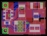
Well got some 22uf caps for the OVP boards and whipped up a few yesterday. I must say it's tedious work.. hehe but I have never made more than one or two at a time this time I made 3 and then 6 and only had 1 bad connection on the outside zener that was an easy fix with the iron. I also wanted to see if this flikr thing works ok.. :)


IMG_4082 by Kizdawg, on Flickr


IMG_4092 by Kizdawg, on Flickr
 
Last edited:


benmwv

0
Joined
Sep 10, 2010
Messages
1,380
Points
48
Nice! I think these are the first real pics of the OVP boards? Maybe even the first made? I haven't made any of them.

Have you ran one open load yet?
 

AnthoT

0
Joined
Jan 14, 2012
Messages
2,133
Points
48
yeah nice work kizdawg, pretty nice reflow also ;) i may just suggest using less solder paste when reflowing, you don't need much :)

+rep to you :D
 
Last edited:

benmwv

0
Joined
Sep 10, 2010
Messages
1,380
Points
48
I just got a scope and I will be back home in a week and a half so I can do some testing then. I'm gonna order an assortment of caps and see what I can figure out. I have been thinking maybe a very small cap (like 0.1uf) between ld+/- and then 22uf on input and between ld+/gnd.
 
Joined
Feb 7, 2012
Messages
977
Points
0
Thanks I havent got arround to testing any of them yet puting together a mits500 tonight crossing my fingers!@ if that all goes well then I'll stick on some resistors and test some out. Me Duh! Open load!!! Oh yeah they have OVP... :banghead: I'm actually allmost done the mits so I will let ya know how they test out..

Well I tested one was set for 105ma with a 1.8ohm resistor I still only have 6 diodes on the test load so I was reading 176ma then i simulated diode failure for about 2mins with no load and nothing happened.. then I hooked it back up and was reading 176ma so I would say the OVP worked fine it didnt heat up or anything without the load. I am going to test a 1013ma next and see how that goes.
 
Last edited:
Joined
Feb 7, 2012
Messages
977
Points
0
Well I made 2 at 1013ma and tested them the first one tested fine at 1095ma (6diodes) and then i unhooked the diode leads and it got quite hot so I stopped when I retested it after it cooled off it was pooched 500ma ish but bounced arround alot and was not stable at all. The second was the same at 1095ma and I unhooked the diode and it seemed fine ran it about 30secs no load and when I hooked it back up it was fine at 1095ma. So then I started looking at the bad driver and I can see that one of the pins on D2 is not connected to the pad. So that must have killed it. Very tiny pads on D2 I am going to inspect them all alot closer now.
 
Joined
Dec 27, 2011
Messages
2,062
Points
48
I just got a scope and I will be back home in a week and a half so I can do some testing then. I'm gonna order an assortment of caps and see what I can figure out. I have been thinking maybe a very small cap (like 0.1uf) between ld+/- and then 22uf on input and between ld+/gnd.

Good for you Ben! What did you end up getting?
 
Joined
Feb 7, 2012
Messages
977
Points
0
Well I figured out this test load. Geese it was simple I'm bypassing the switch and just cliping my diode - on the diode pins so I can test with 1-6 diodes by just moving the clip over to the next diode So I tested the drivers on 4 diodes and hey 1088ma So I decided to paralell them and I got 2170ma so I'm prety happy with the results. Hmm did someone design a board with paralelled drivers on 1 board somewhere in this or was I dreaming..
 

benmwv

0
Joined
Sep 10, 2010
Messages
1,380
Points
48
Good for you Ben! What did you end up getting?

Tektronix 2201 :D Its a bit of an older model but it's digital with storage and it was cheap! (very important for a teenager with no job :p)

I really like the CRT too.

I barely got to try it out and I have no clue how the storage works. Manual here I come!
 
Joined
Feb 7, 2012
Messages
977
Points
0
Dang we all should get a group buy going for equiptment. I havent turned on my benchtop since I killed the mits500 I sent to wanaburn.. There is a deal right now with newark that will get you a free bluetooth adapter for any UMMM Agilent HH DMMeter comes with software I believe.
 
Last edited:

Blord

0
Joined
Dec 24, 2007
Messages
5,356
Points
0
You may have read the story about the failure of the dual Ben boost driver in my 2.8W BIG BOY build. I have found out that the total output of 2.2A is too much for two drivers. Especially for the high Vf needed for the 9mm 445nm diode. The diode need 4.8V to operate at this current while a 5.6mm 445nm diode is .5V lower.

I have separated and tested each driver from the dual setup and the stable current is 900mA. It can't maintain the current at 1040mA or higher. First 10-15 seconds is good but then the output collapses. All drivers were adequate heatsinked.

My next goal is a triple Ben boost setup. I still want to boost 2.2A from 3x parallel 18650 cells. See how that works out :)
 
Last edited:
Joined
Feb 7, 2012
Messages
977
Points
0
That's ggood to hear. These 9mm 445's are turning out to be quite different than the 5.6's I had mentioned doing a triple BB build a while back but was talked out of it three would easily fit on a saik heatsink. Maybe I'll try that on the 9mm saik later I'm still not happy with that build.
 

benmwv

0
Joined
Sep 10, 2010
Messages
1,380
Points
48
Could have sworn I made a post a couple hours ago, guess it didn't get through :thinking:

Anyways I was saying that I think the reason Blord had trouble with the drivers is because the sot-23-5 package isnt very good as far as heatsinking goes. I'm making a fork with the LLP 3x3 package that has a thermal pad. Im trying to decide if I should make it with a pot, what do you guys think? It shouldn't affect price or size very much. actually what I have so far is smaller than whats in the OP, with some nice heatsinking.
 
Joined
Dec 27, 2011
Messages
2,062
Points
48
Could have sworn I made a post a couple hours ago, guess it didn't get through :thinking:

Anyways I was saying that I think the reason Blord had trouble with the drivers is because the sot-23-5 package isnt very good as far as heatsinking goes. I'm making a fork with the LLP 3x3 package that has a thermal pad. Im trying to decide if I should make it with a pot, what do you guys think? It shouldn't affect price or size very much. actually what I have so far is smaller than whats in the OP, with some nice heatsinking.

Well, I know our AWOL friend RHD is not a fan, but I still think that with a GOOD pot you have a lot more control.

First, you can dial in more specific currents more easily. Second, you can change your mind later without yanking resistors and soldering. I have several drivers right now that I don't have all the parts I need to build and I could be using them for different diodes if it were easier to change them. Third, you don't have to do as much work as a seller. You CAN set up the current for the buyer, but in some cases with a savvy buyer you can just test to make sure it works and send it out.

I think the key is getting a GOOD pot. You want one that isn't going to die after a few adjustments and you want one that is easy to use so the user doesn't tear it up trying to adjust it. If you use a standard enough landing pad you could even offer up a parts list with a choice of pots, depending on what you want to spend and what you think you need for a particular application.

Well, that was longer than it needed to be - but I like the idea! :D
 

benmwv

0
Joined
Sep 10, 2010
Messages
1,380
Points
48
Well, I know our AWOL friend RHD is not a fan, but I still think that with a GOOD pot you have a lot more control.

First, you can dial in more specific currents more easily. Second, you can change your mind later without yanking resistors and soldering. I have several drivers right now that I don't have all the parts I need to build and I could be using them for different diodes if it were easier to change them. Third, you don't have to do as much work as a seller. You CAN set up the current for the buyer, but in some cases with a savvy buyer you can just test to make sure it works and send it out.

I think the key is getting a GOOD pot. You want one that isn't going to die after a few adjustments and you want one that is easy to use so the user doesn't tear it up trying to adjust it. If you use a standard enough landing pad you could even offer up a parts list with a choice of pots, depending on what you want to spend and what you think you need for a particular application.

Well, that was longer than it needed to be - but I like the idea! :D

Ha, I already knew what RHD would think of the idea :p Haven't heard from him in like 2 weeks, I wonder whats up.

I like to have pots because I hate always having to calculate and order the resistors. If you want to change the current you may not have the right resistors and then you have to order them. I have a pretty large assortment of low value 0805 resistors though so I can make just about any current I want on these drivers.

If I put a pot on it it definitely wouldn't be a high quality one. It would be one of those hard to adjust micro pots :D

I decided to just use resistors for now, but it won't be very hard to add a pot later. Ive been working on this for the past hour and a half:
attachment.php

On the bottom side right underneath the IC will be bare copper and when you are reflowing you can put a little chunk of copper on that spot with some solder paste. Then that piece of copper can be used to heatsink it to whatever else. This should make a much better thermal connection than heatsinking through the plastic like we are doing now. I'm also going to be experimenting with some smaller inductors.

The board is 9x12mm. Look good?
 

Attachments

  • LLP 3x3 v3.PNG
    LLP 3x3 v3.PNG
    44.2 KB · Views: 372


Top