Welcome to Laser Pointer Forums - discuss green laser pointers, blue laser pointers, and all types of lasers

LPF Donation via Stripe | LPF Donation - Other Methods

Links below open in new window

ArcticMyst Security by Avery

FREE DIY open source BOOST driver!!! Tested & working!!

Joined
Aug 11, 2009
Messages
21
Points
0
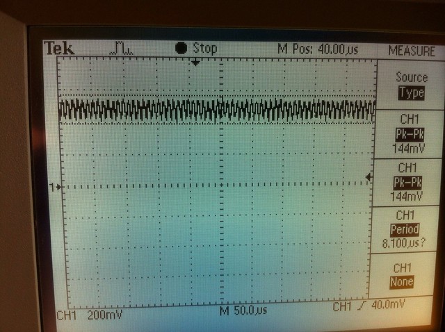
So, just to make sure, when deciding on the current for these drivers, we should take into account a 40 mA (rhd) to 152 mA (tsteele) ringing? In other words, the output might go as high as 20-76mA above what it's set to? Thanks for troubleshooting that startup spike away tsteele :beer:


Joined
Dec 27, 2011
Messages
2,062
Points
48
I don't know, if you look at this DC graph of the 22uF waveform...


10x Probe, 478mA, 22uF, DC, running (measure) by tsteele93, on Flickr

It looks to me like each tick mark is 40 mV which equals 40mA.

So if you count the ticks up from 0 volts (the number 1 with the arrow beside it on the left side of the screen - or the middle of the screen) to 480mV/480mA you will be at just about the centerline of the waveform. That leads me to believe it is running about 40mV/40mA above 480mV/mA as a max. So it LOOKS to me LIKE you would need to account for the diode seeing a high of 520mA.

Does that make sense to anyone else, or am I not understanding this?

EDIT: looking closer, the measurement is ~140mV which would indicate a 70mA over swing on the target current. I may still be doing something wrong, or this driver may still be showing too much ripple.
 
Last edited:
Joined
Jan 14, 2011
Messages
3,816
Points
63
I think that for most drivers, that kind of ripple is... reasonable. I would think that a 12x would be able to handle 520mA for a microsecond. Point is, HUGE start-up spikes are dangerous, but regular ripple isn't that bad. Tom, if you want to scope the output of the Flex (if you have one), then you'll probably see some ripple on that order too. But that's just a hypothesis.
 

ARG

0
Joined
Feb 27, 2011
Messages
6,772
Points
113
I'm not very electronical, and I don't really understand capacitors. I have a 500mA benboost with 10uF caps and a 12x diode.

Would a 47uF electrolytic capacitor bridging the diode leads remove the start up spike? or any other capacitor across the diode leads? I don't have very steady hands and soldering tiny components is a nightmare for me.
 
Joined
Mar 29, 2011
Messages
1,056
Points
48
I'm not very electronical, and I don't really understand capacitors. I have a 500mA benboost with 10uF caps and a 12x diode.

Would a 47uF electrolytic capacitor bridging the diode leads remove the start up spike? or any other capacitor across the diode leads? I don't have very steady hands and soldering tiny components is a nightmare for me.

It would be better to use a higher value cap on the output between Vout and GND. the cap between the L+ and L- is additional and will work well only if you have a big enough cap (Vout/GND) doing most of the job first!

EDIT: now I'd like to add this too as it might cause confusion in the future.

Increasing the output caps above the needed values can some times cause worse results than expected like increase in voltage spike. So be careful when adding additional caps.
 
Last edited:
Joined
Dec 27, 2011
Messages
2,062
Points
48
I don't have a flex, I have some of Tom's (foulmist) drivers I could scope and I may have some of Moh's linears laying around to compare to - I will have to check.


EDIT: now I'd like to add this too as it might cause confusion in the future.

Increasing the output caps above the needed values can some times cause worse results than expected like increase in voltage spike. So be careful when adding additional caps.

Most of the data sheets seem to suggest that 66uF is safe (and even recommended), so I wouldn't be too worried about going to that level. I think we can just stack caps if we need to. Right?

Thanks for the kind words RHD. This is something that the community should have been doing when you guys first shared the design. I have learned a lot over the past few weeks doing this, so it has been very rewarding for me as well. Thanks to everyone who has helped figure this out and provided analysis. It looks like this is a learning area for most of us with the oscilloscope involved. I still feel like I've probably made it harder than needed as you suffered through my growing pains. Hopefully this will make it easier in the future. :D
 
Last edited:
Joined
Dec 27, 2011
Messages
2,062
Points
48
I was looking at ICs today and stumbled on this interesting bit of info...

https://www.national.com/ds/LM/LM2731.pdf

When selecting a ceramic capacitor, only X5R and X7R di- electric types should be used. Other types such as Z5U and Y5F have such severe loss of capacitance due to effects of temperature variation and applied voltage, they may provide as little as 20% of rated capacitance in many typical applications. Always consult capacitor manufacturer’s data curves before selecting a capacitor. High-quality ceramic capacitors can be obtained from Taiyo-Yuden, AVX, and Murata.

SELECTING THE OUTPUT CAPACITOR
A single ceramic capacitor of value 4.7 μF to 10 μF will provide sufficient output capacitance for most applications. If larger amounts of capacitance are desired for improved line support and transient response, tantalum capacitors can be used. Aluminum electrolytics with ultra low ESR such as Sanyo Oscon can be used, but are usually prohibitively expensive. Typical AI electrolytic capacitors are not suitable for switching frequencies above 500 kHz due to significant ringing and temperature rise due to self-heating from ripple current. An output capacitor with excessive ESR can also reduce phase margin and cause instability.

In general, if electrolytics are used, it is recommended that they be paralleled with ceramic capacitors to reduce ringing, switching losses, and output voltage ripple.
 
Last edited:
Joined
Mar 29, 2011
Messages
1,056
Points
48
I was looking at ICs today and stumbled on this interesting bit of info...

https://www.national.com/ds/LM/LM2731.pdf

When selecting a ceramic capacitor, only X5R and X7R di- electric types should be used. Other types such as Z5U and Y5F have such severe loss of capacitance due to effects of temperature variation and applied voltage, they may provide as little as 20% of rated capacitance in many typical applications. Always consult capacitor manufacturer’s data curves before selecting a capacitor. High-quality ceramic capacitors can be obtained from Taiyo-Yuden, AVX, and Murata.

Tom,

I mentioned this a couple of times but as if everyone ignored it :D
 
Joined
Sep 20, 2008
Messages
17,622
Points
113
There is a reason the values in the Data Sheet are suggested..

That is one hell of a spike at startup with 10uF Caps...:eek:


Jerry

You can contact us at any time on our Website: J.BAUER Electronics
 
Last edited:

Blord

0
Joined
Dec 24, 2007
Messages
5,356
Points
0
I have build a dual Ben Boost driver. The combined output isn't what I expected.
Both drivers are electrically isolated from each other and also isolated from the pill.
If measured separately one driver has an output of 1030mA and the other driver has 1070mA. The combined output measures only 1.7A and it should be 2.1A :confused:

The power is delivered by 3x Sanyo 18650 in parallel.

Does the drivers somehow interact with each other when both are connected ?

IMG_0528.jpg
 
Last edited:

benmwv

0
Joined
Sep 10, 2010
Messages
1,380
Points
48
What kind of test load are you using (how many diodes)? The drivers may be overloaded.

Say you are using six 1n540x (3A) diodes and a one ohm resistor. At 2A the diodes will be dropping about 0.9v and there will be 2v over the resistor for a total of 7.4v over the test load. That's a lot more than a single 445nm diode would need, and might be too much for the drivers to handle. They might be pulling 5 or 6A trying to reach that current which would also drop some voltage just in the connections between the batteries and the drivers.

It could also have something to do with the inductors being too close together, I don't know.
 

Blord

0
Joined
Dec 24, 2007
Messages
5,356
Points
0
Yes I am using 6 diodes from the 3A testload. You say at 2A they drop 0.9 each ? So the total drop is 5.4V. Try with 5 diodes then.

What can I do about separating the inductors ? Put a sheet of metal in between ?
 

benmwv

0
Joined
Sep 10, 2010
Messages
1,380
Points
48
You have to account for the ~2v dropped by the resistor too. Try using 4, maybe 3 diodes and see what happens.
 

rhd

0
Joined
Dec 7, 2010
Messages
8,475
Points
0
Yes I am using 6 diodes from the 3A testload. You say at 2A they drop 0.9 each ? So the total drop is 5.4V. Try with 5 diodes then.

What can I do about separating the inductors ? Put a sheet of metal in between ?

(6 x 0.9) + 1.7 = 7.1
(6 x 0.9) + 2.1 = 7.5

Either way, your realized Vf, or your target current's associated Vf, on your testload, are about 2.5 to 3V higher than a real 445nm diode would have. In fact, I'm impressed that you were even able to hit 1.7A, because you're trying to make the driver do ~60% more boosting than it is typically thought to max out at.

On another note, how did you reflow your boards? Because the bottom one has an improperly attached inductor from the looks of it. It looks quite crooked, implying a less than ideal contact with the PCB pads.
 
Last edited:


Top