Welcome to Laser Pointer Forums - discuss green laser pointers, blue laser pointers, and all types of lasers

LPF Donation via Stripe | LPF Donation - Other Methods

Links below open in new window

ArcticMyst Security by Avery

FREE DIY open source BOOST driver!!! Tested & working!!

Hiemal

0
Joined
Dec 27, 2011
Messages
1,443
Points
63
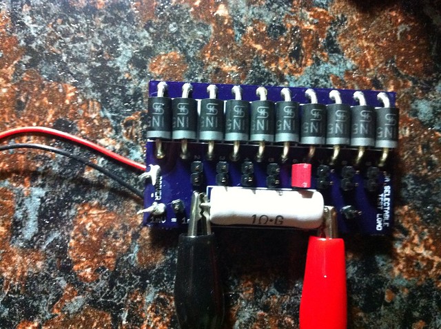
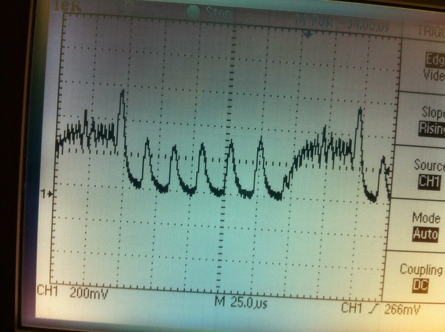
Tom, in order to scope the output of the driver, you need to hook up the grounding clip to whereever the diode's negative is. Then, take the probe and hook it to the positive output of the driver. You'll need to run it with a testload obviously, but, this way you'll be scoping whatever it is your diode will see. Those slopes in some of those scope pictures look a lot more like what the ripple should be.

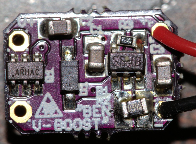
Also, it can't be the wrong IC. If it was the wrong ic it wouldn't work, period.


rhd

0
Joined
Dec 7, 2010
Messages
8,475
Points
0
Can you try a test with a lithium ion as the power source?

Does your test load use a wirewound resistor?

LeQ: if it was the 525 khz version of the IC, it might work (poorly). I think they have the same pinout.
 
Last edited:

Hiemal

0
Joined
Dec 27, 2011
Messages
1,443
Points
63
Ah, yeah, that would cause issues... a lot of issues actually.

Wonder if that's what is causing all of these problems.

EDIT; I just calculated the frequency of that ripple in those new scope pictures...

Around 500 khz.
 
Last edited:
Joined
Dec 27, 2011
Messages
2,062
Points
48
I will try to hook the scope up the way LeQuack is telling me to do it.

The test load is Jufran's test load and it has a large 1 ohm resistor. Here it is hooked up to the voltmeter to check the current. I was getting .476A on a driver set up as .478A I think, so it seemed to be working properly as far as current goes. And that would make me think it was wired up correctly and I had the right voltage and setting on the PSU.


Untitled by tsteele93, on Flickr

I can do an Li-ion to power the driver. That is a good idea. Get rid of any PSU that could be causing a sine wave or anything like that.
 

rhd

0
Joined
Dec 7, 2010
Messages
8,475
Points
0
Le Quack:

What took you to 500 khz?

If you're correct, then it's very likely the wrong IC version on these boards, and that would explain everything.
 

benmwv

0
Joined
Sep 10, 2010
Messages
1,380
Points
48
Tom, can you get us a good macro of the board you are using (make sure the text on the IC is readable)?
 

Hiemal

0
Joined
Dec 27, 2011
Messages
1,443
Points
63
Le Quack:

What took you to 500 khz?

If you're correct, then it's very likely the wrong IC version on these boards, and that would explain everything.

7170607991_d026078c1d_z.jpg


the ripple on this one, using the math I used. It's ROUGHLY 500 khz, anyway.
 
Joined
Mar 29, 2011
Messages
1,056
Points
48
Yeah this time I did the math correct I think :D

it's around 500KHz

Wait isn't current ripple supposed to measured in AC coupling?

I see DC on the photos. :thinking:
 
Last edited:
Joined
Dec 27, 2011
Messages
2,062
Points
48
Tom, can you get us a good macro of the board you are using (make sure the text on the IC is readable)?

Yeah, I will be driving back home today so it will be sometime tonight before I can do it. I am about 5 or 6 hours away from home right now.


7170607991_d026078c1d_z.jpg


Period on that one is almost exactly 175 uS = 0.000175s

Frequency = 1/Period

F=1/0.000175s

F= 5,715 hz

What am I doing wrong with my math?
 
Last edited:

Hiemal

0
Joined
Dec 27, 2011
Messages
1,443
Points
63
Yeah, I will be driving back home today so it will be sometime tonight before I can do it. I am about 5 or 6 hours away from home right now.


7170607991_d026078c1d_z.jpg


Period on that one is almost exactly 175 uS = 0.000175s

Frequency = 1/Period

F=1/0.000175s

F= 5,715 hz

What am I doing wrong with my math?

Period is measures from one cycle to the next; aka, peaks to peak. Not across the entire screen. :)
 

rhd

0
Joined
Dec 7, 2010
Messages
8,475
Points
0
Here is what we need to see:

- One clear scope of the boost being run from a single lithium ion cell, with testload that uses a resistor that is not wirewound, and a scope that is properly connected.

We've got a bunch of different images, and it's not clear what's what. Lets get the PSU out of the equation, by using a decent cell, and lets get a clear shot of what the output looks like.
 
Joined
Dec 27, 2011
Messages
2,062
Points
48
Period is measures from one cycle to the next; aka, peaks to peak. Not across the entire screen. :)

That is what I was doing. Each large box on the screen is 25uS and there are 7 boxes from peak to peak. I'll upload a picture of what I am talking about. I'm guessing that I am reading the scope wrong? At least this will make it clear how I'm reading it wrong. :D


benboostscopemarkup by tsteele93, on Flickr

Here are the benboost macro shots.


benboostmoh1 by tsteele93, on Flickr

I know you don't care about the back, but here it is anyway.


benboostmoh2 by tsteele93, on Flickr

Also, I was doing some searching and saw that Eudamonium has done some work on this IC in the past, don't know if there is any info we can scavenge from this thread?

http://laserpointerforums.com/f42/my-lm3410x-based-boost-converters-spark-driver-part-1-a-47741.html

I'm going to see if I can hook a battery up and see what we get. I'm still not 100% sure how to hook up the scope, but I will try LeQuack's idea. Not sure how to get around the wirewound resistor though. I don't know if I have any other 1ohm resistors around and I definitely have no easy way to put them on the test load yet. I will be ordering some soon, but I don't have them yet.

Is that important? If I am using a battery, it seems like we will be eliminating any source of A/C corruption. I can try scoping across the LD+ and LD- if that is better than scoping across the resistor.
 
Last edited:

rhd

0
Joined
Dec 7, 2010
Messages
8,475
Points
0
I'll toss another idea out there. I'll preface by saying that Mosfets aren't my thing, and I never add them to my boards.

If you think about the theory of operation, the mosfet protection circuit is relying on the voltage differential between Gate and Source being higher than its threshold. In a normal (say linear) driver, this would be no problem. That voltage differential would be there, 100% of the time, once the driver was up and running.

But with a switching IC, I'm not completely certain that this would be the case. I don't know that the VIn of the boost circuit has a duty cycle of 100%. If it doesn't, then the mosfet could be trying to switch off and on a gajillion (well 1,600,000) times per second. It might / might not be able to keep up with that.

Make any sense?
 
Last edited:

Hiemal

0
Joined
Dec 27, 2011
Messages
1,443
Points
63
I'll toss another idea out there. I'll preface by saying that Mosfets aren't my thing, and I never add them to my boards.

If you think about the theory of operation, the mosfet protection circuit is relying on the voltage differential between Gate and Source being higher than its threshold. In a normal (say linear) driver, this would be no problem. That voltage differential would be there, 100% of the time, once the driver was up and running.

But with a switching IC, I'm not completely certain that this would be the case. I don't know that the VIn of the boost circuit has a duty cycle of 100%. If it doesn't, then the mosfet could be trying to switch off and on a gajillion (well 1,600,000) times per second. It might / might not be able to keep up with that.

Make any sense?

The mosfet isn't a part of the switching circuit though. I do see what you might be saying though, and the mosfet... well, may have problems.

If the voltage of the battery gets too low then the mosfet might not see all of the voltage it needs, and may potentially heat up/explode/smoke because it's stuck in its linear region.

And I checked up the part number on the LM3410, and it's the 1.6 mhz one. So, that's not the issue.


Top