foulmist
0
- Joined
- Mar 29, 2011
- Messages
- 1,056
- Points
- 48
Is it? Step me through the math on that. I'm sure you're right.
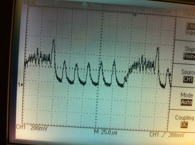
I think it's a huge ripple pictured, but not really a startup spike, because isn't that just during normal operation? He said that those last three were the same shots, but "after" startup, which I would take not necessarily to mean a startup spike, but rather just the ongoing ripple. (which is just as bad)
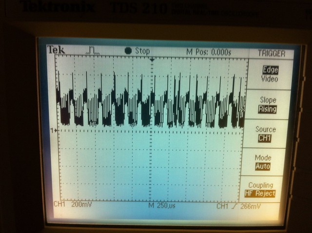
yeah i think it's an awful ripple too.
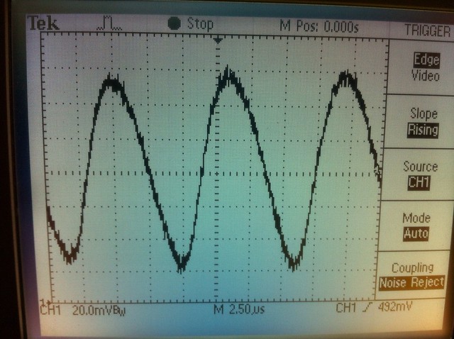
here it's 4 divisions from start to end of the signal so.
2.5us = 0.0000025 seconds.
F = 1/s
F = 1/0.0000025 = 400000 * 4 divisions = 1600000Hz = 1.6MHz
:wave:


")