phenol
0
- Joined
- Oct 30, 2007
- Messages
- 533
- Points
- 18
Thats a 300MHz scope, but when i limit its bw to 20 MHz the loop doesnt pick any noise whatsoever...
I am not saying that this or that chip is bad per se, it is the layout and component selection that make the difference. For instance, inductors, even those shielded ones, radiate detectable amounts of hf noise, as do high current traces. If the fb loop of one such driver passes under or close to a power inductor, it may render the whole design inherently unstable.
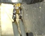
as a precaution against switching transients, i have soldered 0805 100n caps directly on the leads of my laser diodes.
I am not saying that this or that chip is bad per se, it is the layout and component selection that make the difference. For instance, inductors, even those shielded ones, radiate detectable amounts of hf noise, as do high current traces. If the fb loop of one such driver passes under or close to a power inductor, it may render the whole design inherently unstable.
as a precaution against switching transients, i have soldered 0805 100n caps directly on the leads of my laser diodes.


") You high voltage guys you.
You high voltage guys you.