Welcome to Laser Pointer Forums - discuss green laser pointers, blue laser pointers, and all types of lasers

LPF Donation via Stripe | LPF Donation - Other Methods

Links below open in new window

ArcticMyst Security by Avery

FEELER: Ultra-High Current Test Load

Joined
Jan 14, 2011
Messages
3,816
Points
63
Hey everyone.

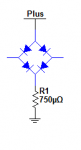
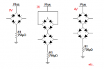
So I designed a test-load for personal purposes - namely, for testing drivers that shoot way above 10A in output current (designed it to be able to handle 30A... may need to make two of them and parallel them for a current driver design that spits up 45A :p ).

However, this driver would have various settings and would be useful - i.e. accurate - at around 1A and above.

That said, this wouldn't be particularly cheap. We're probably looking at $45 each test load, unheatsinked, which is a large investment. Heatsinked (meaning getting a CPU heatsink and thermally gluing it to the top of the board) would probably increase price $10-$20 - but I don't plan on heatsinking them, at least not initially. I probably wouldn't sell these to a store for retail because the demand isn't too high. However, I could stock about 5 at a time or so and buy parts as necessary if people would be interested.

Anyway, so I figured I would throw this up here just in case people were interested.


Joined
Dec 27, 2011
Messages
2,062
Points
48
Have you made one yet? I'd like to see it. That isn't a bad price to handle that kind of current. And most of us have some old cpu or memory heat sinks laying around that we could add some cooling with.
 
Joined
Jan 14, 2011
Messages
3,816
Points
63
Haven't made one yet, but test loads are pretty fool-proof when it comes to designing :p

I won't have it made until I get back from Chicago, unfortunately (means ~1.5 months). But I will probably have the parts waiting for me for when I get back.

I am going to use this for a test load for my 45A IR diode array driver that I designed (also pretty hefty).

To put things into perspective, this is about 5cm x 8 cm. Not all that small. But, properly heatsinked, it should be able to pull 20A all day and 30A for a good while too.

And to be fair... I will probably end up selling them for $40-$45. Don't want to make too much off of these (they are about $35 in parts).
 
Last edited:
Joined
Sep 12, 2007
Messages
9,399
Points
113
The only diodes that need that kind of current are 2V, so one of these and a resistor like this would be capable of 100A. Supply your own cooling, and hook up as so:

attachment.php


Why pay $45 for 30A when you can have 100A for $8 :beer:
 

Attachments

  • 100A test load.png
    100A test load.png
    2.2 KB · Views: 395
Joined
Jan 14, 2011
Messages
3,816
Points
63
I suppose that's true!

But you never know when you're going to need a ridiculously large current for... say, a Phlatlight!
 
Last edited:
Joined
Dec 27, 2011
Messages
2,062
Points
48
The only diodes that need that kind of current are 2V, so one of these and a resistor like this would be capable of 100A. Supply your own cooling, and hook up as so:

attachment.php


Why pay $45 for 30A when you can have 100A for $8 :beer:

How will you read the current? Is that going to be 1mV=1mA?

Also, the resistor is 100A but the bridge rectifier is only good to a mere 50A. :D
 
Last edited:
Joined
Feb 10, 2012
Messages
330
Points
0
How will you read the current? Is that going to be 1mV=1mA?

Also, the resistor is 100A but the bridge rectifier is only good to a mere 50A. :D

My guess is that when used as a bridge rectifier, the current flows in series through a diode pair alternately ( only 2 diodes are in use during each 1/2 cycle).

The test load has the diode pairs in parallel (all diodes in use), therefore effectivly doubling the rating which is spec'ed for bridge mode...
 
Last edited:
Joined
Sep 12, 2007
Messages
9,399
Points
113
How will you read the current? Is that going to be 1mV=1mA?

No, it will be 75mV=100A. This is a standard, and many ammeters are compatible if you don't feel like doing the math. This for example.

You'd be a fool to use a 1Ω sense resistor for high current. It would need to be rated for at least 100W - substantially more if you wanted any decent accuracy.
Resistance increases with temp.

And of course the rather large problem: It would drop 100V.

the bridge rectifier is only good to a mere 50A. :D

As Multimode pointed out, when used as a bridge rectifier, it can support 50A. That's 50A PER DIODE. You'd be using it differently - notice it's a pair in parallel.

But you never know when you're going to need a ridiculously large current for... say, a Phlatlight!

It is easily scalable (for an extra $2), just as any test load:

attachment.php
 

Attachments

  • 100A test load scalable.png
    100A test load scalable.png
    10.9 KB · Views: 748
Last edited:
Joined
Jan 14, 2011
Messages
3,816
Points
63
I suppose the reason mine is so expensive is because I am using 12 diodes for high voltage selection ability. My diodes are cheaper than the things you have. I am just using 12 .5V equivalent diodes so you can test between 1.5 and 6V.
 
Joined
Sep 12, 2007
Messages
9,399
Points
113
0.5V at what current? It's likely closer to 0.7V or more at the max rated current.
 
Joined
Jan 14, 2011
Messages
3,816
Points
63
It's about .5V at around 3A, up to around .54V at 10A. That's what I designed it for.
 
Joined
Dec 29, 2009
Messages
3,136
Points
63
Can you just grab a full-wave rectifier offa just some random PSU that you have for parts? I'm assuming everyone else here is an electronics packrat too, right?


right?


:anyone:
 
Joined
Jan 14, 2011
Messages
3,816
Points
63
Heh. I'm an electronics packrat too. I just like getting nice, clean circuits. And I love SMD components that fit nicely onto a board :D
 
Joined
Sep 12, 2007
Messages
9,399
Points
113
Can you just grab a full-wave rectifier offa just some random PSU that you have for parts?

Unless it has a hole that you can bolt a heat sink onto, it's probably only good for a few amps even if it's relatively big. Most of them don't have part numbers, so you either guess from the current in the original circuit, or you test destructively I suppose. :eek:
 

Hiemal

0
Joined
Dec 27, 2011
Messages
1,443
Points
63
I can tell you right now you'll be very hard pressed to find any diodes that can handle upwards of 50-100 amps unless they're brick package. And I don't even understand the purpose behind using such an incredibly high current...you wouldn't be able to use PCB traces for that unless they're basically board sized ones. You're going to run into a lot of issues. Even the tiniest of resistances in high current loads cause problems, and heat. Lots of heat.
 
Joined
Jan 14, 2011
Messages
3,816
Points
63
Well, I found a few diodes capable of 30A in D2PACK. And I checked a handy trace width calculator for 10A and I have MORE than enough trace width to handle 10A.

The purpose behind such a high current is being able to confirm that my 45A laser driver is working properly. Otherwise... I'm sort of screwed out of $100! :D


Top