I used a breadboard to make this driver but wanted a more permanent driver (as I use the breadboard for other stuff). I also made a test load but that's boring.
Simple Driver using RS board 276-159B. There are actually 2 boards when you buy this (or there was when I bought them 15 yrs ago).
One switch for discharging cap through 1k Ohm (or whatever) Resistor.
One switch for selecting max of 250 mA or 500 mA (by using the 5 Ohm resistor by itself or 2 in parallel).
30 Ohm pot I had lying around
LM317 I had lying around. Pinouts labeled I, O, and A (If you don't know what they mean then nevermind )
)
Parts are inserted on opposite side of board and soldered where big black dots are.
Pretty easy. I'm going to build this sometime this week.
Side Note: I received my modules from DTR, pressed the diode I found in a 12x DVD burner (knowing it wasn't prob going to burn tape) anyway and created my own LED :yh: Now that I think about it I probably LEDed it before I even built the driver. I set my PS to about 3.5 volts and touched the leads. About what I expected but it was a good learning experience. Man this stuff is tiny.
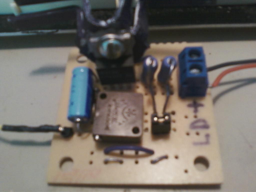
Photo of built driver. Instead of a switch to change max current, I used a jumper (just below the two resistors). With jumper-500mA. Without jumper-250mA.
Sorry for crappy cellphone pic.

Simple Driver using RS board 276-159B. There are actually 2 boards when you buy this (or there was when I bought them 15 yrs ago).
One switch for discharging cap through 1k Ohm (or whatever) Resistor.
One switch for selecting max of 250 mA or 500 mA (by using the 5 Ohm resistor by itself or 2 in parallel).
30 Ohm pot I had lying around
LM317 I had lying around. Pinouts labeled I, O, and A (If you don't know what they mean then nevermind
Parts are inserted on opposite side of board and soldered where big black dots are.
Pretty easy. I'm going to build this sometime this week.
Side Note: I received my modules from DTR, pressed the diode I found in a 12x DVD burner (knowing it wasn't prob going to burn tape) anyway and created my own LED :yh: Now that I think about it I probably LEDed it before I even built the driver. I set my PS to about 3.5 volts and touched the leads. About what I expected but it was a good learning experience. Man this stuff is tiny.
Photo of built driver. Instead of a switch to change max current, I used a jumper (just below the two resistors). With jumper-500mA. Without jumper-250mA.
Sorry for crappy cellphone pic.

Attachments
Last edited:


