Welcome to Laser Pointer Forums - discuss green laser pointers, blue laser pointers, and all types of lasers

LPF Donation via Stripe | LPF Donation - Other Methods

Links below open in new window

ArcticMyst Security by Avery

Driver for the new 505nm and 480nm diodes

Joined
Jun 22, 2011
Messages
2,431
Points
83
I'm looking for suggestions of drivers for the new 505nm and 480nm diodes. Can be forum-built or Chinese.

I'd prefer a boost (voltage gets a bit above 7V at high currents) that can be used with an external pot for analog modulation. Something similar to the blackbuck 8 but for 0-500mA instead of 8A.

Doesn't have to be exceptionally small, I'll probably build them in boxes.

If no driver like that is available I'm considering using an LM317 with 3 batts instead.
 
Last edited:


Joined
Dec 15, 2014
Messages
6,782
Points
113
Hi,
The Nano from DTR it can be set to 275,500 and 1.1MA , 275 and 500 mA are the most suitable for the diode 505 or480nm. Being 500mA pushing and 275mA conservative.
The thread state all the info so this is what i set mine to mostly 275mA . The data shows 125mA but testing shows how much further they can do.
DTR has testing for these diodes on his site. The Nano is a Buck/Boost driver ..

Rich:)
 

Eracoy

0
Joined
Jul 21, 2014
Messages
173
Points
43
Survival Laser has a linear driver for the 70-500mA range, but the pot is on the board so it might take a bit of modification. I ordered one of those for my blue and a couple of the boost drivers DTR sells for my green 505's
 
Last edited:
Joined
Sep 20, 2013
Messages
17,402
Points
113
I got the nano from DRT too. Though it is made to have only the three current sets, I believe I can make it work at 350 mA after I get it and measure the three resistors used to set the current scales. I'll post what I learn for anyone trying to get a different current than 275 mA.
 
Joined
Dec 15, 2014
Messages
6,782
Points
113
Hi,
I also used an X Boost set to 280mA for the 480nm diode .. Thats if you can get them.. I really wish Jordan would start selling the X Boost again ,i don't know if Angelos still makes them or he subs them out now. he's been off line for about 2 years now. Where are you Lazeerer ?????

Rich:)

Rich:)
 
Joined
Sep 20, 2013
Messages
17,402
Points
113
Have you tried to email Angelos lately? I haven't, but it would be worth a try. I have two of his email addresses. No, I can't give them out as they were given to me by Angelos and was asked not to divulge them to anyone. Last time I emailed him was about two years ago.
 
Joined
Jun 22, 2011
Messages
2,431
Points
83
Thanks for the suggestions but I'm really bent on having an external pot for modulation. Maybe I'll have to build my own linear but I want to avoid using 3 batts.
 
Joined
Sep 20, 2013
Messages
17,402
Points
113
Good luck, Atomicrox. I'm sure you will come up with something you can live with. :D
 
Joined
Jun 22, 2011
Messages
2,431
Points
83
Here's what I'm thinking of building if I don't find a proper driver:
r08exi.png

Sorry for the crappy schematic, I don't have a proper design software on this machine.
The resistor in parallel works as a way to lower effective resistance (can't source a cheap multiturn pot with lower ohms)

Unless my math is wrong this should allow me to vary current from about 20mA to almost 500mA. It won't be linear (most of the range will be useless) but I plan on using a multi-turn pot (link below) to make it reasonable.
3590S-2-101L 100 Ohm BOURNS Rotary Wirewound Precision Potentiometer Pot 10 Turn | eBay


Another option would be this:
LM317 adjustable current source/regulator
Seems to be linear but voltage drop will be huge.


Either way I might use a single batt and a step-up converter like this one:
DC-DC USB 2~24V to 5~28V 2A Boost Step Up Adjustable Regulator Power Module | eBay


What do you guys think? Any reason it won't work?
 
Last edited:
Joined
Sep 20, 2013
Messages
17,402
Points
113
Wow. That is a lot of after thought to get to use an LM317 to drive these diodes. Theoretically it should work, but it is going to cause more heat than necessary and will be a lot to cram into a handheld host. At least you are limiting the current or there would be even more heat to sink. Your first circuit is causing most of the current to go through your pot, which isn't good. The second one has a minimum 2 watt resistor, or better 3 watt to cram in there. Then a boost circuit? A boost driver would do a better job and take up a lot less space. I'm sure there are other things i could find if I spent more time, but don't have it right now.
 
Joined
Jun 22, 2011
Messages
2,431
Points
83
The host is probably going to be a (handheld) box, I like them more than flashlight hosts because they don't require a tripod to stay put and allow more space :)

I know this circuit isn't the best, I'm still open to a better solution, as long as I can adapt it with an external pot.
 
Joined
Mar 27, 2011
Messages
504
Points
43
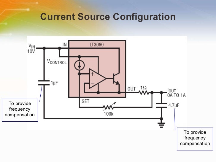
It shall works, alternatively you can use the 500mA version: LT3085.
the inner block are just like our "everyday" chinese linear driver
which uses one LM385 OpAmp and one transistor/mosfet, only the Linear Tech ICs are monolithic all in one chip.

One thing needs to be taken care of:
Although their dropout voltage is 300mA, but they have Vcontrol dropout which is ~1.26V, not sure if it will become total dropout voltage if configured as current source
if the case is YES, then you need a minimum of (0.3+1.26+Vf) voltage to run the laser diode (Vf=V forward laser diode)
 
Joined
Jun 22, 2011
Messages
2,431
Points
83
Gotcha, thanks!

I don't want to use the LT3085 because it comes only in SMT packages. My soldering skills ain't good enough for that ;)

I'll test it with a variable power supply and if I end up needing too much input voltage I'll just add the step up converter before it and use a single batt. Do you foresee any trouble with that setup?
 
Joined
Mar 27, 2011
Messages
504
Points
43
That would be great. pre boosting before bucking.
I'm sure there will be no problem except for its inefficiency

And don't forget to add heatsink to both PCB,
linear driver tends to produce more heat per V*I produced
compared to switching regulator.
 
Last edited:


Top