Welcome to Laser Pointer Forums - discuss green laser pointers, blue laser pointers, and all types of lasers

LPF Donation via Stripe | LPF Donation - Other Methods

Links below open in new window

ArcticMyst Security by Avery

Driver built for 445nm A140 Diode

Joined
Jan 20, 2011
Messages
23
Points
0
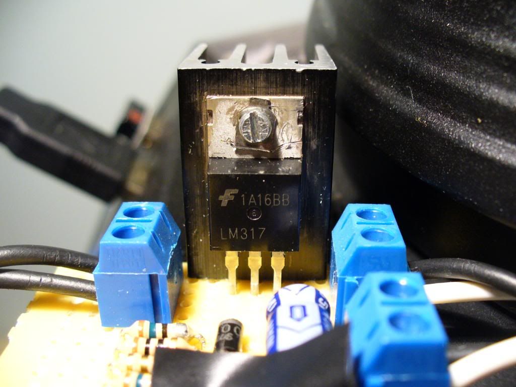
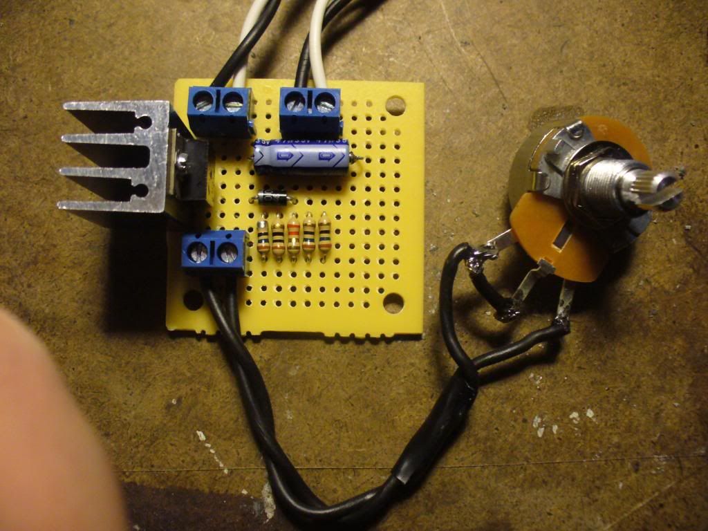
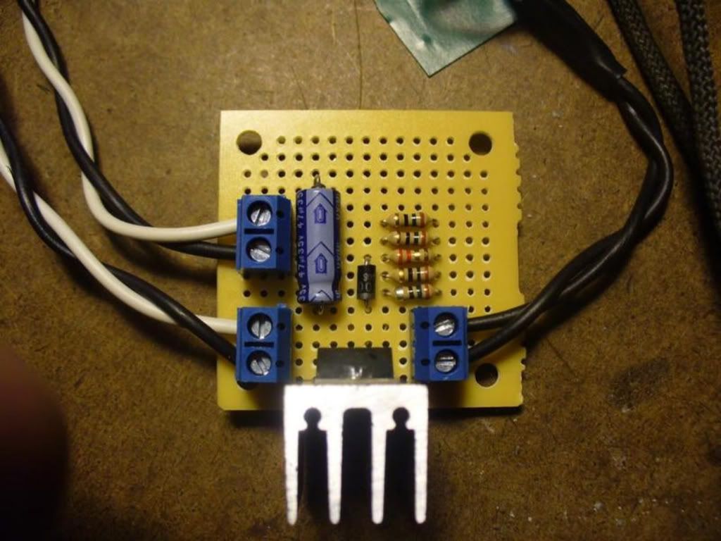
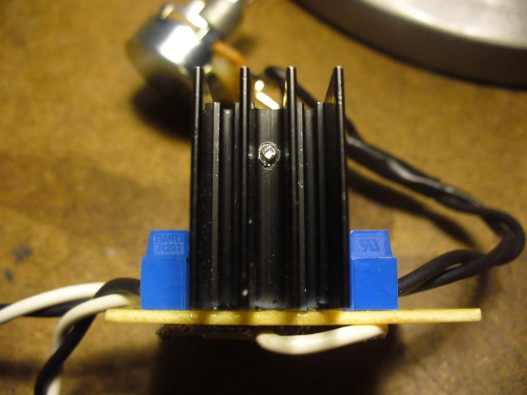
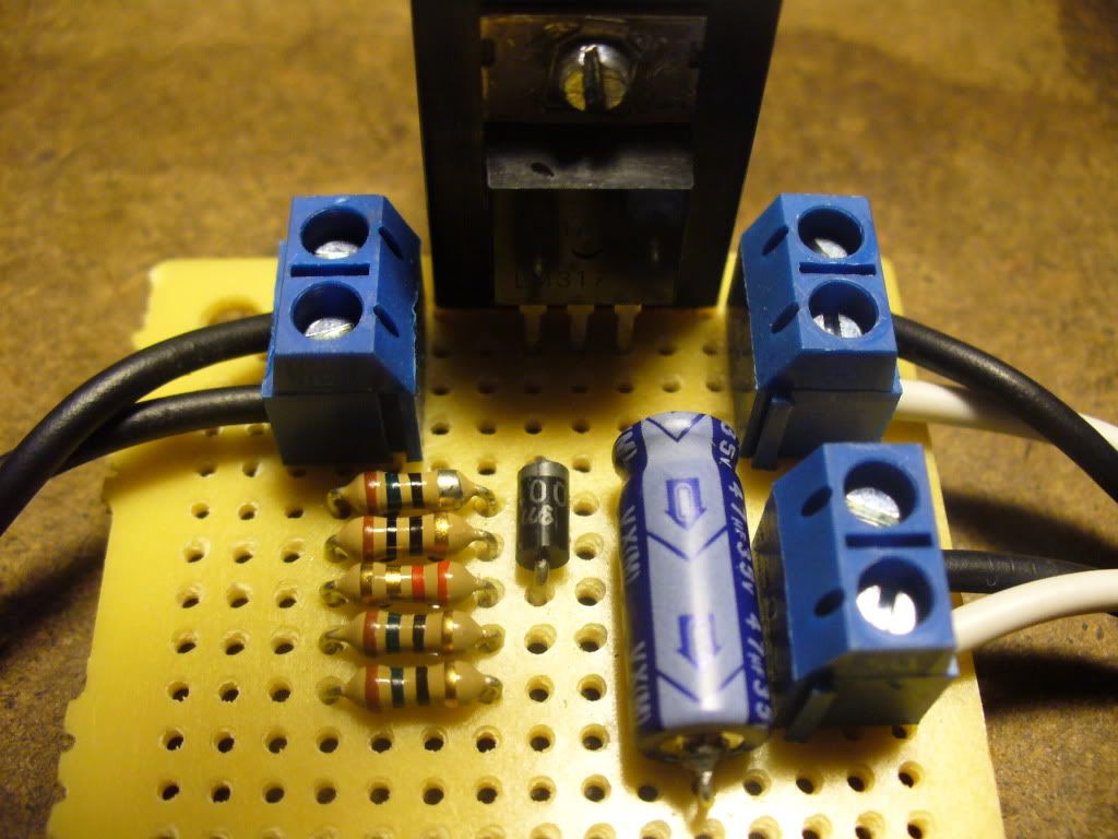
This is my latest circuit for my 445nm A140 Diode. I am posting to give ideas maybe to people looking to build a linear driver. I am also looking for any suggestions for next design (anything to add or change).

Parts:

-LM317t Adjustable voltage regulator attached to TO-220 Heatsink using Arctic Silver and Screw
-25 ohm Rheostat (best pot i can get from radioshack)
-3x15ohm 1x10ohm 1x2.2ohm in parallel = 1.55ohm(wanted precisely 980ma max) also helps with heat because only 1/4watt each
-1N4001 Diode
-Axial Lead 47uF 35w Electrolytic Capacitor
-PC Board Terminals (new awesome discovery I made)

hope someone is helped by this and that yous like the design...

073.jpg

063.jpg

062.jpg

034.jpg

046.jpg
 
Last edited:


anselm

0
Joined
Nov 22, 2010
Messages
2,448
Points
0
That's a funny way to wire up the potentiometer...:thinking:
I myself usually just connect the middle pin and one of the outer pins, but not all three!
 
Joined
Jan 20, 2011
Messages
23
Points
0
That is just the way i saw it done on some utube video a while ago. Thought that was how had to be done? is it not??
 
Joined
Aug 7, 2010
Messages
2,086
Points
0
I don't know what anselm means by that. All the drivers has that connections, no worry.
I don't see any difference wiring just the middle and the left or right pin.
 

GBD

0
Joined
Oct 25, 2010
Messages
783
Points
0
Heres my driver layout. its a simple LM317 regulator as shown. the only modifications are a TO-220 diode on the input (to prevent reverse connection) and a poor man's TTL via a mosfet shorting the output.
Sadly I dont have the board I made anymore (I junked it as I dont use linear drivers anymore).
Here is the board layout:

mylinbmp.jpg


And the thread where I posted a schematic (Except a resistor is now used on the gate, board mound rather then external):

http://laserpointerforums.com/f44/why-not-lm317-instead-flexdrive-59074.html

Id post a PCB file if I could figure out how to upload it on the forum..

EDIT: I noticed this was an old revision of the PCB.. which has a trace error on it (the output isnt connected).
It was still layed out simular to this, just the error needed to be fixed. best not to use this one.
 
Last edited:

GBD

0
Joined
Oct 25, 2010
Messages
783
Points
0
I tried.. it says invalid file. (my filename ends with .pcb)
 
Joined
Aug 7, 2010
Messages
2,086
Points
0
Oh the forum don't allow that. You'll need to upload to some file host on the internetz ;)
 

anselm

0
Joined
Nov 22, 2010
Messages
2,448
Points
0
just rename the pcb file's extension or zip it.
05112.png

Connecting it like you have it doesn't change anything to the way I do it.
For it to work, you really only need to connect the middle pin and one of the outer pins.
You can connect the middle pin to the other outer pin, but it doesn't accomplish anything.
 
Joined
May 4, 2009
Messages
5,443
Points
113
Nice set up, you have done it all correct, a pot may be connected like that it's no problem at all.
the only way you could improve this is to put it on a purpose made ckt board for it.

Good Job :)
 
Joined
Jan 20, 2011
Messages
23
Points
0
Nice set up, you have done it all correct, a pot may be connected like that it's no problem at all.
the only way you could improve this is to put it on a purpose made ckt board for it.

Good Job :)

Thank you very much I was feeling quite disappointed as this is my best driver to date and I felt proud of its layout, design and neatness. Yet you are the first to say anything good about it!:D Thanks for the post:thanks:
 
Joined
Aug 7, 2010
Messages
2,086
Points
0
Thank you very much I was feeling quite disappointed as this is my best driver to date and I felt proud of its layout, design and neatness. Yet you are the first to say anything good about it!:D Thanks for the post:thanks:

Man.. your driver is very neat! Thats the reason all that discussion started on this page (about other drivers and so). Looking professionally built driver like yours inspire us to make our own. GOOD JOB!
 

kozack

0
Joined
Feb 28, 2011
Messages
8
Points
3
Nice build! I am about to start soldering the parts together too.
Are there any alternatives to the diode used in the driver? :thanks:
 

rhd

0
Joined
Dec 7, 2010
Messages
8,475
Points
0
I think there's a problem with using 1/4 W resistors in parallel like that.

Ignoring the rheostat, lets just consider the resistors - and specifically, it's the 2.2 I'm worried about.

The problem is, that your 2.2 Ohm resistor is going to shoulder MORE of that than all of the other resistors combined. ALL of the other resistors parallel to 3.3 Ohms. Add the 2.2 Ohm, and you get a final resistance of 1.32 Ohms (good so far)

Wattage @ 2.2 Ohm Resistor: 1.25^2 / 2.2 = 0.71 W
Total wattage @ all other resistors in parallel: 1.25^2 / 3.3 = 0.47 W

I won't bother to dissect each of the other resistors, because I think they're fine. But that 2.2 Ohm resistor is going to be handling about 0.7 W of power dissipation, which is way beyond it's 1/4 W rating.
 
Joined
Apr 4, 2011
Messages
596
Points
28
Thank you for your post. I got some excellent ideas for heatsinking my LM317s and for using all my 1/4W resistors. :)
 
Joined
Apr 4, 2011
Messages
7
Points
0
Can we get a look at the bottom of the driver, so us noobs can see exactly how everything is hooked up? :kewlpics:


Top