- Joined
- Aug 6, 2010
- Messages
- 382
- Points
- 0
Hi all,
The deeper I get into bench testing the more parts I find I need. When working with the common DDL LM317 driver I was trying to hit a target ma value. Naturally I didn't have the exact resistor and don't need enough parts to justify and order for 1 special resistor. A solution is at hand! It does take a little practice but is very inexpensive. Nichrome wire! If this has been posted I apologize. I searched , didn't find it and wanted to share.
I needed a resistor less than 3ohms but greater than 2.5ohms to achieve an output current of 450ma. Here is a nice calculator to give you the resistance needed just by inputting the ma desired when using the LM317.
LM317 Current Calculator - Electric Circuit
Nichrome wire can be purchased in 10' lengths for $2-$3 free shipping and 30' for less than $5-$6 from ebay.
I needed a 2.8ohm resistor. Like I have that laying around..........:undecided:
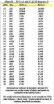
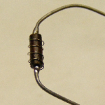
I took an old high value resistor (470K) from some ancient parts I had. It looks like the phenolic type with a carbon core. I used an emery board to remove all markings. Then I soldered the nichrome wire to one side. Next slide your DMM along the length till you have more ohms than you need. I stopped at 3.5ohms and cut the length of 36ga nichrome wire(27ohms per foot) or 2.25ohms per inch. Next was to wrap it around the old resistor and measure the value. I did clean the resistor leads right against the body for a good reading. When you have it close, but higher, 3.1ohms, apply just a tiny bit of flux with a toothpick and solder it to the resistor lead. Flux is needed to solder to nichrome wire. Rosin core just does not work well. The solder will creep up the wire some and hopefully you should be near 2.9ohms. To fine tune it all you need to do is reheat the solder and drag it up the wire just a very little distance and remeasure. If its to low after the the 1st soldering, it can be undone, or marked as its value with a folded piece of tape on the lead for later use.
Next I checked the amount of heat produced. I ran a LPC-815 for 3-5 min constantly and touched the bare wire. It was warm, almost hot holding my finger on it for 15 seconds while running. Many will state that nichrome wire increases resistance with heat. This is true, but if the right gauge is used this presents no problem. My 2.8's current changed 3ma from a cold state to full running with an actual current of 453ma. Works for me, is cheap and no waiting to finish a build! I can and have put heat shrink on them or Liquid Tape if fear of a possible short exists. 34ga is .005(0.13mm) dia. A better choice for less heat would be 34ga at 450ma as it is producing just over 1/2watt of heat.
In the picture the wire is new and is away from the form just a bit as it is slightly springy. This is easily solved. After the wire is soldered to the 1st side, it can be connected to a battery very quickly for a second till red hot.
This removes the springiness, forms an oxide coating on the wire that does not conduct well at all so the wire can be wrapped with the coils touching if needed! A little gap between winds is preferred. All that is needed is to clean the end to be soldered.
Hope you enjoyed the post.
The deeper I get into bench testing the more parts I find I need. When working with the common DDL LM317 driver I was trying to hit a target ma value. Naturally I didn't have the exact resistor and don't need enough parts to justify and order for 1 special resistor. A solution is at hand! It does take a little practice but is very inexpensive. Nichrome wire! If this has been posted I apologize. I searched , didn't find it and wanted to share.
I needed a resistor less than 3ohms but greater than 2.5ohms to achieve an output current of 450ma. Here is a nice calculator to give you the resistance needed just by inputting the ma desired when using the LM317.
LM317 Current Calculator - Electric Circuit
Nichrome wire can be purchased in 10' lengths for $2-$3 free shipping and 30' for less than $5-$6 from ebay.
I needed a 2.8ohm resistor. Like I have that laying around..........:undecided:
I took an old high value resistor (470K) from some ancient parts I had. It looks like the phenolic type with a carbon core. I used an emery board to remove all markings. Then I soldered the nichrome wire to one side. Next slide your DMM along the length till you have more ohms than you need. I stopped at 3.5ohms and cut the length of 36ga nichrome wire(27ohms per foot) or 2.25ohms per inch. Next was to wrap it around the old resistor and measure the value. I did clean the resistor leads right against the body for a good reading. When you have it close, but higher, 3.1ohms, apply just a tiny bit of flux with a toothpick and solder it to the resistor lead. Flux is needed to solder to nichrome wire. Rosin core just does not work well. The solder will creep up the wire some and hopefully you should be near 2.9ohms. To fine tune it all you need to do is reheat the solder and drag it up the wire just a very little distance and remeasure. If its to low after the the 1st soldering, it can be undone, or marked as its value with a folded piece of tape on the lead for later use.
Next I checked the amount of heat produced. I ran a LPC-815 for 3-5 min constantly and touched the bare wire. It was warm, almost hot holding my finger on it for 15 seconds while running. Many will state that nichrome wire increases resistance with heat. This is true, but if the right gauge is used this presents no problem. My 2.8's current changed 3ma from a cold state to full running with an actual current of 453ma. Works for me, is cheap and no waiting to finish a build! I can and have put heat shrink on them or Liquid Tape if fear of a possible short exists. 34ga is .005(0.13mm) dia. A better choice for less heat would be 34ga at 450ma as it is producing just over 1/2watt of heat.
In the picture the wire is new and is away from the form just a bit as it is slightly springy. This is easily solved. After the wire is soldered to the 1st side, it can be connected to a battery very quickly for a second till red hot.
This removes the springiness, forms an oxide coating on the wire that does not conduct well at all so the wire can be wrapped with the coils touching if needed! A little gap between winds is preferred. All that is needed is to clean the end to be soldered.
Hope you enjoyed the post.


") 34ga would be a few more wraps and a lot cooler.
34ga would be a few more wraps and a lot cooler.