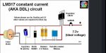
Welcome to Laser Pointer Forums - discuss green laser pointers, blue laser pointers, and all types of lasers

LPF Donation via Stripe | LPF Donation - Other Methods

Links below open in new window

ArcticMyst Security by Avery

Corect test load?

Joined
Aug 27, 2010
Messages
28
Points
0
hi
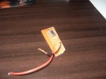
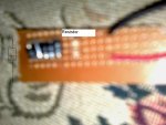
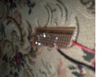
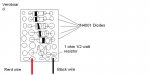
im on my way to making a driver for my laser
but first i made the the test load, it consists of 5 N41001 diodes and 1 1ohm 1/2 watt resistor
i have read about test loads and wat they are meant to do
but im just want to run this by every1 that can tell me that ive done it correctly and sorry for the blurry vision
 

Attachments

  • painted.JPG
    painted.JPG
    70.5 KB · Views: 172


Joined
Sep 12, 2007
Messages
9,399
Points
113
I assume you mean 1N4001 which is rated for 1A, but a half watt resistor can only handle 0.7A

Are they in parallel? Unless you have some fancy wiring underneath the board, that's wrong. I only see 4 diodes. Your color-coding of polarity is also backwards. We'd need a pic of the underside to be sure.

Also, which driver?
 

Kevlar

0
Joined
Apr 26, 2010
Messages
1,353
Points
48
Yeah, like Cyparagon said, a nice CLEAN, close-up shot of the underside is needed to be sure. That pic is pretty blurry but I think I see 5 diodes.
 
Joined
Aug 27, 2010
Messages
28
Points
0
yea sorry i meant 1N4001, yea theres 5 of them heres the picturres of the driver im going to be applying the test load to, theres the test load and the soldering om the test load, and the driver (sorry for the blurry vision again, its the best i can get)
 

Attachments

  • front.JPG
    front.JPG
    49.2 KB · Views: 98
  • driverr.JPG
    driverr.JPG
    42.5 KB · Views: 38,445
  • test load soldering.JPG
    test load soldering.JPG
    49.1 KB · Views: 121
Last edited:
Joined
Sep 12, 2007
Messages
9,399
Points
113
That's not much better. Maybe if you can draw it or borrow someone else's camera? It still looks to me like they're in parallel.

What power source and diode are you using?

You don't need a test load for linear regulators. Just put your ammeter on the output.
 
Joined
Aug 27, 2010
Messages
28
Points
0
hope this pic helps
the power source will be about 7.2v
and the laser diode is from a 16x dvd drive (red)
 

Attachments

  • test load from paint.JPG
    test load from paint.JPG
    34.3 KB · Views: 224

Kevlar

0
Joined
Apr 26, 2010
Messages
1,353
Points
48
It's still really hard to tell, do you have a macro setting on that camera?

Like Cyp said, it sure looks like they are in parallel and they should be in series.
 
Joined
Sep 20, 2008
Messages
17,622
Points
113
In your drawing...put lines between the diodes to
show how they are connected...
As is in that drawing all the ends of the Diodes and
Resistor are floating... (not connected to anything but
the board)..

Jerry
 
Last edited:


Top