Welcome to Laser Pointer Forums - discuss green laser pointers, blue laser pointers, and all types of lasers

LPF Donation via Stripe | LPF Donation - Other Methods

Links below open in new window

ArcticMyst Security by Avery

Contact Board For Laser

Joined
Feb 1, 2017
Messages
670
Points
0
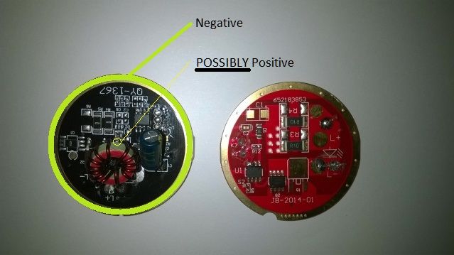
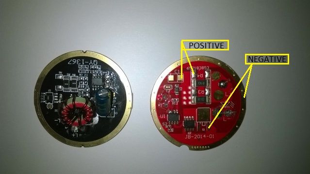
I found these 2 contact board circuit , they belonged to 2 different models of flashlights with led , now the question is : what is the diode laser can I connect ?
And above all , there is something which has to be unsoldered ?
Or should I just connect red wire and black wire ?


xfz4o5.jpg


10s69w7.jpg


Excuse me eh ....are at the beginning.....!
 
Last edited:


Joined
Sep 4, 2016
Messages
551
Points
63
Are you trying to use the LED driver to power a laser diode or are you trying to use the circuit to get power to a laser diode driver?
 
Joined
Sep 4, 2016
Messages
551
Points
63
Do you have a multimeter? If so, put one lead on the positive terminal point on the side with no components and probe with the other to find a point with a resistance at or very close to 0Ω. Might still be best to remove the components though.

It also appears that there is a VIA visible on the positive on the black driver. It should go through right under the torroid on that board and should act as a suitable location to pull positive from.
Really not sure on that red board though.
 
Joined
Sep 4, 2016
Messages
551
Points
63
I'm having a very hard time understanding exactly what it is that you are trying to achieve here.
I am ASSUMING that you are trying to build a laser and wish to use ONE of these boards as a way to get power to a proper laser diode driver.
If so, with the BLACK board, the OUTER metal ring would be negative.
That little hole that goes though near the center of the board should go to a good spot to get positive from. It looks to me that it goes to one end of the wire on the torroid but I cannot be certain of this.

xfz4o5_zpskbvmx6yi.jpg


Best bet is still to de-solder all of the components and check using a meter.
 
Last edited:
Joined
Feb 1, 2017
Messages
670
Points
0
Instead of another disc ,the red one to the right , there you just need to solder the positive and negative as in the drawing of the + and -- printed ?
 
Joined
Sep 4, 2016
Messages
551
Points
63
Only in it's original usage as a flashlight driver. Without using a meter, I cannot say. Maybe someone else can spend a few minutes looking at the pictures and see something I am missing.

EDIT: I missed something obvious.
See those seven holes that go through the red board? Using this as a contact board, those should be positive, there or the empty pad marked "R4" on the side towards those holes.
Then just pull negative from that outer ring. About to edit a picture to show exactly where I mean.


EDIT 2: PICTURE
xfz4o5_zpsihegwquy.jpg
 
Last edited:
Joined
Feb 1, 2017
Messages
670
Points
0
It's okay , thank you, you've been very kind ! unfortunately, when you are not experienced ,things become difficult !
 

BobMc

0
Joined
Apr 23, 2016
Messages
3,685
Points
113
I've built half a dozen or so in flashlight hosts and used their contact board. I've always removed all the components drilled a small hole in the center for the positive wire than sodered the ground to the outer ring. Tested, made sure their was no continuity between the two. (Food for thought) :thinking:. If you can, post some pictures of your build when your finish. (plus beam shots ). :)
 
Last edited:
Joined
Feb 1, 2017
Messages
670
Points
0
Hi Bob ,Can you post a photo of how you have done ? I these 2 contact board circuit I have drawn out the 2 torches led of a different brand !
 

BobMc

0
Joined
Apr 23, 2016
Messages
3,685
Points
113
Hi Bob ,Can you post a photo of how you have done ? I these 2 contact board circuit I have drawn out the 2 torches led of a different brand !

Please search for a build thead I made " luxpro lp600 build' . I'd link to it but my iPhone being stubborn . There are some pictures there that show what I did. Hope they help. :)

It's probably operator error, but I'm blaming it on the phone, :D
 
Last edited:
Joined
Feb 1, 2017
Messages
670
Points
0
Wow nice build Bob :drool: you have the seem led driver red round form ,
So i must unsolder everything there is on the circuit and leave only where there is written V+/V- ? and then drill a hole in the center of the driver ? or do I connect only V+ and V- ?
 

BobMc

0
Joined
Apr 23, 2016
Messages
3,685
Points
113
Wow nice build Bob :drool: you have the seem led driver red round form ,
So i must unsolder everything there is on the circuit and leave only where there is written V+/V- ? and then drill a hole in the center of the driver ? or do I connect only V+ and V- ?

Glad you found it and thanks :)

Yes, all your using the board for is to move current from the battery to the driver without shorts ( very important ) test, test , test . Also what driver are you using?
 

BobMc

0
Joined
Apr 23, 2016
Messages
3,685
Points
113
I'll take a driver from Jordan ! perhaps a 5ampere on diode 6W

Sounds good, I'm guessing it's a 044 diode? Your pushing that diode past the recommended amps ( 4.5 ) but I built one pushing it that hard and she works just fine. Just know you are taking a chance. Also make sure you heat sink the driver well, it will need it. Hoping the best. Finger on the :drool: button. :)


Top