Welcome to Laser Pointer Forums - discuss green laser pointers, blue laser pointers, and all types of lasers

LPF Donation via Stripe | LPF Donation - Other Methods

Links below open in new window

ArcticMyst Security by Avery

Case Grounding Question

Adams

0
Joined
Jul 20, 2010
Messages
9
Points
0
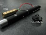
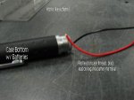
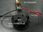
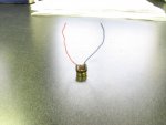
I just ordered some modules for a product my company is developing. The only way I can get the modules to work is to jerry rig the ground wire on the module into the grounded case of another laser pointer pen.

How do I go about grounding the wire in a small working area? i.e. as small a space as possible so I can just connect the leads to a battery.

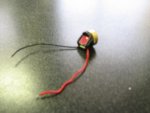
Using Instapark 532 nm 5mW Laser Module.
 
Last edited:


Morgan

0
Joined
Feb 5, 2009
Messages
2,174
Points
0
Are these for handheld pointers or labby style modules? I'm guessing at 5mW a labby is not on the cards!

Photos of the host and module will help but green modules are usually case positive so use the pointer body, (if it is a pointer), as a conductor and put the battery in reverse direction to conventional flashlights. A little searching on the forum would have got some results on this.

Are you going to show us more or are we just being used for R&D work? Which company is it? What products do you have at the moment? (Not and invitation to SPAM, just trying to make your aquaintance :D ) Go introduce yourself in the, "Welcome", section if you're going to be joining us regularly.

Welcome to LPF! :wave:

M
:)
 

Adams

0
Joined
Jul 20, 2010
Messages
9
Points
0
Thanks for the reply Morgan.

You're correct about it being a handheld style.

I'm not too familiar with the technical jargon, so after searching, I figured it would save time to ask directly.

When I find the camera, I will try to post some photos.

I am an intern for Adams (mechanical engineer, electricity is not my specialty), should be top search in Google, can't post exactly what the product is or the full company name (hint: consumer goods), but a little imagination can help deduce that quickly (competition reasons).

I guess what I am asking is how to bypass the whole case positive thing. Why won't it work when directly connected to battery and what can I use other than the case to make it work?

This is the module I am using. I put the batteries in the pen case and leave the cap off then touch the red lead to the case threads and the black lead to the negative battery terminal.
http://www.instapark.com/laser-pointers/5ww-532nm-green-dot-laser-module.html
 
Last edited:

Morgan

0
Joined
Feb 5, 2009
Messages
2,174
Points
0
I see, good luck with your internship, (I couldn't see where at, Adams Engineering founded in 1977? or Adams Engineering in Gloucestershire?)

Yep, pretty standard module. I don't know that company or that product but it may well be possible to find a much cheaper solution, check out the, 'Companies', and 'Reviews', sections. Looks like a quality unit though.

You can certainly get it to work by connecting straight to a power source, you don't have to use the body as a conductor. You just have to be careful to electrically isolate the power source from the case. This does either mean running seperate wires for the battery connections; or, if you still want to use the body as a conductor, you need to seperate the outside of the module from the body. Unfortunately, there is no way round this. Certainly for the higher powers that we often like to use the case being positive, and therefore using the body as a conductor, also has the benefit of better thermal transfer so it's something we kind of like. With 5mW you shouldn't even need to consider this heat though.

If you're planning on using button batteries, it may do you a favour to buy a few different dirt cheap, poor quality green keyring pointers, (a couple of bucks each at most), and see how they do it. My approach may be to simply insert a thin plastic sleeve to electrically isolate the battery compartment from the body and run a negative wire past the batteries; or place a similar thin plastic sleeve over the module itself, (thin heatshrink?), and still use the tailcap and body to form part of the circuit. I can't tell from the pic on the site if there's a momentary switch on the driver board or not, (I suspect not for some reason), but maybe you can confirm this in some of your own photos... When a camera is available of course ;) .

I hope that helps and others may even have other ideas.

M
:)
 

Adams

0
Joined
Jul 20, 2010
Messages
9
Points
0
QC had camera.

I completely ignored your location, but we are based in Texas, so Google's GeoIP tracking probably didn't help you out when trying to find us, sorry. To clarify, we make golf related products.

But from the photos, the laser works perfect when I hold the leads on the case of the other pointer like described, but doesn't do a thing when connected directly to button cell. There is no switch.
 

Attachments

  • IMG_9026.jpg
    IMG_9026.jpg
    32.4 KB · Views: 137
  • IMG_9028.jpg
    IMG_9028.jpg
    36.4 KB · Views: 122
  • IMG_9029.jpg
    IMG_9029.jpg
    34 KB · Views: 147

HIMNL9

0
Joined
May 26, 2009
Messages
5,318
Points
0
Too low current !!

CR2032 are unable to give any decent current, they are clock batteries, after all .....

Try with 2 alkaline AAA or AA batteries in serie ..... if this work, is the 3V battery that cannot give you all the needed current, as i suspect .....
 

Adams

0
Joined
Jul 20, 2010
Messages
9
Points
0
I've tried that with both AA and AAA and got the same results as the button cell.
 

Morgan

0
Joined
Feb 5, 2009
Messages
2,174
Points
0
Odd. If you think about the test in the photos, you are doing exactly the same thing connecting to 2 AAs. Case takes the positive rail and the end of the battery is, well, the negative end of the battery. I assume the laser pointer you're using there is either AA or AAA? No special batteries in there? I can't see any reason why resistance in the case would affect anything, but I could be corrected. I'd try some other batteries and be sure of polarity, you may be able to read the correct voltage on the battery but under load they may not be putting out enough.

M
:)
 
Joined
Jan 8, 2009
Messages
3,145
Points
83
Greens are case positive IIRC. I know your using the drivers direct leads I cant
explain it, but the greens as a rule are wired up the same as ir diodes.

What is that mass of wires out the rear of the modules themselves?
 
Joined
Dec 29, 2009
Messages
3,136
Points
63
I've tried that with both AA and AAA and got the same results as the button cell.

You are using 2 AA's, positive to negative, not just one, right?

Black wire of laser---[=AA=}[=AA=}---red wire of laser

Use fresh alkalines, not heavy duty alkalines. I'd recommend buying a 3V cr123a for testing, but they are expensive at stores, when online they are $1 plus shipping.
 

Adams

0
Joined
Jul 20, 2010
Messages
9
Points
0
.

What is that mass of wires out the rear of the modules themselves?

See attached photos. I received one DOA so I tore it apart to see the innards, typical engineering fashion. I believe it houses the crystal the IR beam hits, why it is wired? I haven't a clue.
 

Attachments

  • IMG_9033.jpg
    IMG_9033.jpg
    44.3 KB · Views: 124
  • IMG_9035.jpg
    IMG_9035.jpg
    36 KB · Views: 123

Adams

0
Joined
Jul 20, 2010
Messages
9
Points
0
You are using 2 AA's, positive to negative, not just one, right?

Black wire of laser---[=AA=}[=AA=}---red wire of laser

Use fresh alkalines, not heavy duty alkalines. I'd recommend buying a 3V cr123a for testing, but they are expensive at stores, when online they are $1 plus shipping.

2 AA or 2 AAA in series, wired as you put it. New batteries, standard alkalines, nothing.
 

HIMNL9

0
Joined
May 26, 2009
Messages
5,318
Points
0
@ Adams: well, it IS strange ..... have you tried also connecting the negative to the black wire and the positive to the module body ? (not to the red wire, directly to the brass)


@ jander6442: the drivers normally used on green modules are usually current sinks ..... they don't have a common negative path, the common for current sinks drivers is always the positive ..... what mass you are referring ?
 

Adams

0
Joined
Jul 20, 2010
Messages
9
Points
0
@ Adams: well, it IS strange ..... have you tried also connecting the negative to the black wire and the positive to the module body ? (not to the red wire, directly to the brass)

Eureka! Works perfect, but what use is the red wire if positive cap is supposed to be connected directly to the brass? And now why is the red wire useful only when connected to the case positive pointer?
 
Joined
Dec 29, 2009
Messages
3,136
Points
63
Perhaps it was wired wrong by the manufacturer. Usually the leads will bypass the switch, but I wonder if perhaps the positive lead is connected after the switch or something.

That mystery component looks like it is probably used for optical feedback to regulate output.
 

Adams

0
Joined
Jul 20, 2010
Messages
9
Points
0
Just soldered on a new wire for the original red one. Found it in a drawer. It now works with straight AAA batteries. Bad wire?


Top