Can I modulate FlexMod P3 (3.3) with 24V PWM signal
I know It says 0-5v... but I have o way converting 0-25PWN signal into 0-5V without having reference 5v from somewhere and optocoupler.
Flex mod driven by 24V and I have only 24V PWN signal, driving 405nm laser.
I read somewhere that I can go upto 16V on M+ for modulation.
Can you guys suggest me some great idea when I don't have to add any active components to make it work?
BTW. I have no option but drive FlexMod with 24V, unless I come up with some extra switching DC-DC circuit to drop it to 9-12V etc....
Last edited:


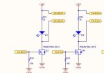
") (10k,2,7k)
(10k,2,7k)