

- Joined
- Aug 25, 2012
- Messages
- 116
- Points
- 0
I know every enthusiast here gets to the point where they want an adjustable power supply to cater to their hobby. Many here also see the mods done to computer power supplies, and the costly purpose-built power supplies on the market. Well, below is my take on the situation.
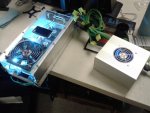
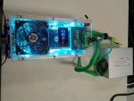
INTRODUCING: SPECTRE'S BLUE ICE MACHINE!
The photos should indicate where the name came from. It was the first thing that popped in my head after the first 'power up'.

It's really not as complex as you might think, but there are several reasons why I went this route, instead of purchasing one off the bay.
1) I need AMPS. I plan on doing some anodizing here eventually and 1.5-3A DC is not going to cut it.
2) I have PC power supplies come by my desk all the time, when their respective PCs fail.
3) I have a lot of scrap electronics parts that make a project like this very affordable. Buying everything outright is obviously foolhardy.
4) It's a challenge and I like it. Why not?
I wanted to make this thing so it would modify any power supply plugged into it, in case the power supply itself failed. That way the PC power supply became a swappable part, not an integral part of the device. The regulator itself has 8x 15A power transistors providing the final power output, thereby making the limiting factor the PC power supply. Need more output? Upgrade your supply. The one I'm using now is an older 500W supply.
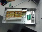
It all started over the course of several years collecting heat sinks, fans, plexiglass, and various components. The original enclosure was some sort of modular tray that went into something else. Either way, it was mostly an empty aluminum box when I got a hold of it. As received, it was a bit too small for the application. I replaced the front, which made it more like a desk drawer instead of an electronics enclosure, with a taller plate of clear plexi, making the entire enclosure taller with a sizeable exhaust vent in the back. The top was cut through the middle, leaving the two side plates and a flange for bolting. The clear plastic made it look great, and allowed for more versatile mounting of fans, controls, etc.
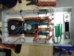
Lots of tedious wiring in the process... Below you can see the two green RSC resistors, which my mistake, were the wrong value.

The next major step was to find a schematic that would work for me. I started off with this one here: [url=http://electronics-diy.com/30v-10a-variable-bench-power-supply.php]30V 10A Variable Bench Power Supply[/URL]
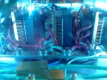
I deviated from the original schematic, namely the power transistors. It calls for 2N3055's, which are great but a TO3 package wasn't easy to work with a heatsink. I opted for 2n6488's, which is the same thing in a more modern TO-220 package. below you can see them pasted to my monster copper heatsinks before bolting them down. Another concern was that the tabs on these are tied to the collector of the transistors. Since they were all electrically common, it wasn't a problem that they were together, but I didn't want any potential for them shorting to the case. To fix this, I mounted them on blocks I cut from cutting board material, HDPE.

The HDPE stock was very easy to cut, drill, tap, and work with in general. Plastic will be the new wood some day!
On the electronics, I knew I had to load down each supplied voltage, otherwise I could not get all the potential I could from the power supply, or at worst, fry it. The 12V rail was obviously going to be regulated for the output. The 5V rail was utilized for the auxiliary equipment: all 6 fans, and the volt/current meter (originally). Turns out, 5VDC is excellent for PC fans. They don't spin so fast and are therefore much quieter. No shortage of flow, either. Anyways, the meter had to be powered by a 9V battery eventually, because the isolated power supply didn't work as it should.
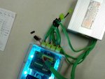
The 3.3V rail was really fun. We all know what 3.3V is good for, right? Flashlight power!!! I took a single flashlight driver and powered 6 cyan 1W LEDs for some case lighting. IMO, way better than any ceramic resistor!!!
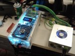
Here's a shot through the front window...

One of the challenges was how to get the ATX connector to hook up to the machine. On the top of the enclosure I mounted a cut-short riser board from one of the dead servers that came through our door. Not only does it break out the power, but it has several little green LEDs for each power rail. Even though I cut off 2/3 of the original board, it all works just as needed.
Below you can see the picture of how power is delivered to the system. On the back I glued 4x fan pigtails to provide power directly to the final power transistors. They needed more juice than that backplane board could ever hope to provide under heavy load!

I must apologize to the masses, I cannot provide any beamshots with this post. But that doesn't mean we can't see any performance. MAX CURRENT SCOTTY!

Yes, that's correct. 23 FRIGGEN AMPS!!! (output leads shorted together)
As I said before, if you bought everything to build this, it would cost a ridiculous amount of money. As far as buying just the components, the most expensive part was the meter/shunt combo. They go for $25 USD on Ebay. I think the rest was somewhere in the $40 range. Not bad, considering the performance.
The thermal management is way over the top for purpose built, but I got all the copper for free from dead PCs. I did buy all the electronic components new, but the support hardware and mounting blocks were things I collected over a long period of time. I still have leftover surplus from collecting things for this. Heatsink anyone?
I had fun building it, and it looks really cool. Lots of shiny anodizing and copper parts glistening in turquoise light. I hope the community can benefit from my experience, and if not, gain some entertainment from my scrapping and tinkering!
INTRODUCING: SPECTRE'S BLUE ICE MACHINE!
The photos should indicate where the name came from. It was the first thing that popped in my head after the first 'power up'.
It's really not as complex as you might think, but there are several reasons why I went this route, instead of purchasing one off the bay.
1) I need AMPS. I plan on doing some anodizing here eventually and 1.5-3A DC is not going to cut it.
2) I have PC power supplies come by my desk all the time, when their respective PCs fail.
3) I have a lot of scrap electronics parts that make a project like this very affordable. Buying everything outright is obviously foolhardy.
4) It's a challenge and I like it. Why not?
I wanted to make this thing so it would modify any power supply plugged into it, in case the power supply itself failed. That way the PC power supply became a swappable part, not an integral part of the device. The regulator itself has 8x 15A power transistors providing the final power output, thereby making the limiting factor the PC power supply. Need more output? Upgrade your supply. The one I'm using now is an older 500W supply.
It all started over the course of several years collecting heat sinks, fans, plexiglass, and various components. The original enclosure was some sort of modular tray that went into something else. Either way, it was mostly an empty aluminum box when I got a hold of it. As received, it was a bit too small for the application. I replaced the front, which made it more like a desk drawer instead of an electronics enclosure, with a taller plate of clear plexi, making the entire enclosure taller with a sizeable exhaust vent in the back. The top was cut through the middle, leaving the two side plates and a flange for bolting. The clear plastic made it look great, and allowed for more versatile mounting of fans, controls, etc.
Lots of tedious wiring in the process... Below you can see the two green RSC resistors, which my mistake, were the wrong value.
The next major step was to find a schematic that would work for me. I started off with this one here: [url=http://electronics-diy.com/30v-10a-variable-bench-power-supply.php]30V 10A Variable Bench Power Supply[/URL]
I deviated from the original schematic, namely the power transistors. It calls for 2N3055's, which are great but a TO3 package wasn't easy to work with a heatsink. I opted for 2n6488's, which is the same thing in a more modern TO-220 package. below you can see them pasted to my monster copper heatsinks before bolting them down. Another concern was that the tabs on these are tied to the collector of the transistors. Since they were all electrically common, it wasn't a problem that they were together, but I didn't want any potential for them shorting to the case. To fix this, I mounted them on blocks I cut from cutting board material, HDPE.
The HDPE stock was very easy to cut, drill, tap, and work with in general. Plastic will be the new wood some day!
On the electronics, I knew I had to load down each supplied voltage, otherwise I could not get all the potential I could from the power supply, or at worst, fry it. The 12V rail was obviously going to be regulated for the output. The 5V rail was utilized for the auxiliary equipment: all 6 fans, and the volt/current meter (originally). Turns out, 5VDC is excellent for PC fans. They don't spin so fast and are therefore much quieter. No shortage of flow, either. Anyways, the meter had to be powered by a 9V battery eventually, because the isolated power supply didn't work as it should.
The 3.3V rail was really fun. We all know what 3.3V is good for, right? Flashlight power!!! I took a single flashlight driver and powered 6 cyan 1W LEDs for some case lighting. IMO, way better than any ceramic resistor!!!
Here's a shot through the front window...
One of the challenges was how to get the ATX connector to hook up to the machine. On the top of the enclosure I mounted a cut-short riser board from one of the dead servers that came through our door. Not only does it break out the power, but it has several little green LEDs for each power rail. Even though I cut off 2/3 of the original board, it all works just as needed.
Below you can see the picture of how power is delivered to the system. On the back I glued 4x fan pigtails to provide power directly to the final power transistors. They needed more juice than that backplane board could ever hope to provide under heavy load!
I must apologize to the masses, I cannot provide any beamshots with this post.
But that doesn't mean we can't see any performance. MAX CURRENT SCOTTY!
Yes, that's correct. 23 FRIGGEN AMPS!!! (output leads shorted together)
As I said before, if you bought everything to build this, it would cost a ridiculous amount of money. As far as buying just the components, the most expensive part was the meter/shunt combo. They go for $25 USD on Ebay. I think the rest was somewhere in the $40 range. Not bad, considering the performance.
The thermal management is way over the top for purpose built, but I got all the copper for free from dead PCs. I did buy all the electronic components new, but the support hardware and mounting blocks were things I collected over a long period of time. I still have leftover surplus from collecting things for this. Heatsink anyone?
I had fun building it, and it looks really cool. Lots of shiny anodizing and copper parts glistening in turquoise light. I hope the community can benefit from my experience, and if not, gain some entertainment from my scrapping and tinkering!
Attachments
Last edited:


