- Joined
- Jan 14, 2011
- Messages
- 3,816
- Points
- 63
Hey everyone. So I was taking a look at some ICs over at Linear Technology and noticed that no one had ever introduced a charge pump driver into the forum. I experimented with them a while back but decided that they probably wouldn't be wanted enough by the forum to warrant the effort of selling them. Then I decided that I should just make them open-source! After all, I am taking the driver basically directly from the datasheet xD
The method of operation of this type of driver is not your typical buck/boost driver. Instead of using an inductor to store energy, it uses something called a "flying capacitor" (sounds like something you'd hear a scientist swear in a cheesy sci-fi movie!) to store energy. Essentially, the driver itself acts as a linear driver, but it increases the input voltage to the necessary amount to drive the load. On the off-state of the driver, the IC draws current enough to charge the capacitor and power the load - it puts the load and flying capacitor in parallel. Then, when it switches on, the capacitor goes in series with the battery, effectively doubling the voltage of the input. With a capacitor on the output, the ripple is smoothed and you get a nice, doubled voltage.
This particular IC is capable of outputting 1x the input voltage, 1.5x the input voltage (clamped at 4.6V) and 2x the input voltage, clamped at 5.1V. That means that, even if you're making your li-ions take a beating and draining them all the way down to 2.7V, it'll still be able to feed 5.1V to whatever diode you need (the remaining voltage will be dropped like in a normal linear driver).
This particular design will be capable of outputting up to 5.1V at 500mA. They are not continuous on the GND path, but most diodes aren't case negative anymore anyways, so I figured that would be fine. This is great for the new Osram 635s and our old 660s because none of those need more than 500mA! Unfortunately, this can't be used to drive a PHR or 12x BR because it can't output enough voltage, but that's okay. We have boosts for those!
Do note that these are not nearly as efficient as standard buck/boost drivers. This is as efficient as a linear driver if you bumped up the voltage to 1x/1.5x/2x the input voltage. But for those that don't care much about efficiency (and who does, with such low-current builds?), these should be great. Tiny foot-print and cheap part list I think will make it a great addition to the forum.
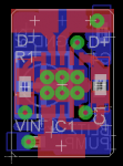
Alright, so here is the schematic file:
.SCH file
And here is the board file:
.BRD file
So a part list!
285mA - 476mA:
1 x LTC3214
3 x 2.2uF 0603-size Ceramic Capacitor
1 x 4.7uF 0603-size Ceramic Capacitor
1 x 7.5k Ohm 0603-size resistor
1 x 5k Bourns Potentiometer, Model TC33
110mA - 288mA:
1 x LTC3214
3 x 2.2uF 0603-size Ceramic Capacitor
1 x 4.7uF 0603-size Ceramic Capacitor
1 x 12.4k Ohm 0603-size resistor
1 x 20k Bourns Potentiometer, Model TC33
That's all, folks! I apologize for not summing it up, but I can assure you that shipping is going to be more expensive than the total order! I apologize for having one part at DigiKey in the 285mA-475mA range. They were only selling that part in quantities of 5000+ at Newark. Enjoy!
Thanks taking the time to read it, I hope this helps the forum!
The method of operation of this type of driver is not your typical buck/boost driver. Instead of using an inductor to store energy, it uses something called a "flying capacitor" (sounds like something you'd hear a scientist swear in a cheesy sci-fi movie!) to store energy. Essentially, the driver itself acts as a linear driver, but it increases the input voltage to the necessary amount to drive the load. On the off-state of the driver, the IC draws current enough to charge the capacitor and power the load - it puts the load and flying capacitor in parallel. Then, when it switches on, the capacitor goes in series with the battery, effectively doubling the voltage of the input. With a capacitor on the output, the ripple is smoothed and you get a nice, doubled voltage.
This particular IC is capable of outputting 1x the input voltage, 1.5x the input voltage (clamped at 4.6V) and 2x the input voltage, clamped at 5.1V. That means that, even if you're making your li-ions take a beating and draining them all the way down to 2.7V, it'll still be able to feed 5.1V to whatever diode you need (the remaining voltage will be dropped like in a normal linear driver).
This particular design will be capable of outputting up to 5.1V at 500mA. They are not continuous on the GND path, but most diodes aren't case negative anymore anyways, so I figured that would be fine. This is great for the new Osram 635s and our old 660s because none of those need more than 500mA! Unfortunately, this can't be used to drive a PHR or 12x BR because it can't output enough voltage, but that's okay. We have boosts for those!
Do note that these are not nearly as efficient as standard buck/boost drivers. This is as efficient as a linear driver if you bumped up the voltage to 1x/1.5x/2x the input voltage. But for those that don't care much about efficiency (and who does, with such low-current builds?), these should be great. Tiny foot-print and cheap part list I think will make it a great addition to the forum.
Alright, so here is the schematic file:
.SCH file
And here is the board file:
.BRD file
So a part list!
285mA - 476mA:
1 x LTC3214
3 x 2.2uF 0603-size Ceramic Capacitor
1 x 4.7uF 0603-size Ceramic Capacitor
1 x 7.5k Ohm 0603-size resistor
1 x 5k Bourns Potentiometer, Model TC33
110mA - 288mA:
1 x LTC3214
3 x 2.2uF 0603-size Ceramic Capacitor
1 x 4.7uF 0603-size Ceramic Capacitor
1 x 12.4k Ohm 0603-size resistor
1 x 20k Bourns Potentiometer, Model TC33
That's all, folks! I apologize for not summing it up, but I can assure you that shipping is going to be more expensive than the total order! I apologize for having one part at DigiKey in the 285mA-475mA range. They were only selling that part in quantities of 5000+ at Newark. Enjoy!
Thanks taking the time to read it, I hope this helps the forum!
Last edited: