Welcome to Laser Pointer Forums - discuss green laser pointers, blue laser pointers, and all types of lasers

LPF Donation via Stripe | LPF Donation - Other Methods

Links below open in new window

ArcticMyst Security by Avery

blanking LM317 + green module

3zuli

0
Joined
May 30, 2009
Messages
810
Points
28
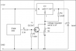
hi, I'm currently modding my spiro and I want to add PWM to the laser. I want to use this schematic (with other transistor)
pwm555.gif


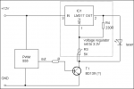
I need to blank green module + LM317 voltage regulator (set to 3.3V). the laser has it's own driver (LM317 just lowers the voltage)
is it possible (safe) to connect it like this? I don't wanna kill my green module :)
attachment.php


I need the answer ASAP :thanks:
 

Attachments

  • blanking.png
    blanking.png
    1.9 KB · Views: 6,813
Last edited:


HIMNL9

0
Joined
May 26, 2009
Messages
5,318
Points
0
Uhm, that one don't look as a current regulator, it look more as a voltage regularor, are you sure it can drive correctly your LD ? ..... in this configuration, there's no current limiting .....
 

3zuli

0
Joined
May 30, 2009
Messages
810
Points
28
I know :p I use LM317 to lower the voltage from 12V to 3.3V for the module. it's an DX 30mW green WITH its original driver
 

HIMNL9

0
Joined
May 26, 2009
Messages
5,318
Points
0
Oh, understood.

Then, just use a transistor (NOT like in your schematic) for pull down the adj pin to GND, for blank it.

I mean, the transistor go in parallel with the trimmer, not in serie, emitter on GND and collector on ADJ pin ..... also, place a 100Kohm resistor between base and GND of the transistor (it's always a good thing to do, when you use a transistor as switch), and the R between the 555 and the base can be anything from 2 to 10 Kohm ..... the transistor can be any NPN common unit, like BC337 or any equivalent, in this configuration, it take at maximum 15 or 20mA.

But remember, LM317 cannot be blanked to zero, without a negative reference ..... it can go at minimum to 1,2V, not less.
 

3zuli

0
Joined
May 30, 2009
Messages
810
Points
28
so I need to do it like this:
attachment.php

at 1.2V it won't lase, so that's ok - and it shouldn't damage the laser... right?
:thanks:
 

Attachments

  • blanking2.png
    blanking2.png
    2 KB · Views: 4,412
Last edited:

HIMNL9

0
Joined
May 26, 2009
Messages
5,318
Points
0
Right, this will blank the LM317 to 1,2V all the times the 555 have positive output, and give you the voltage you set with the trimmer all the time the output from pin 3 of 555 is zero.
 

HIMNL9

0
Joined
May 26, 2009
Messages
5,318
Points
0
How much fast ? ..... i tried them with 10KHz, and they work decently ..... still not tried with thigher frequencies, anyway .....

Also, it depend from the capacitors that are on the original driver of the module ..... if it have 4,7uF or more, this for sure reduce the efficency of the PWM switching a lot, cause the energy stored in the capacitors will "feed" the diode also in the milliseconds when the LM317 is blanked ..... they can be changed, ofcourse, but being SMD components, it require some care and attention .....
 

3zuli

0
Joined
May 30, 2009
Messages
810
Points
28
just noticed the problem :D so can I remove that capacitor? (and replace it with eg. 100nF?) I should be able to do it...
 
Last edited:

dnar

0
Joined
Jun 7, 2010
Messages
608
Points
0
so I need to do it like this:
attachment.php

at 1.2V it won't lase, so that's ok - and it shouldn't damage the laser... right?
:thanks:
I have tried a similar setup, using an NPN open-collector arrangement with the LD wired collector (-) to +3V6 (+).

I also added a resistor across the transistor C and E to provide a "bias" voltage to the LD, resistance selected to obtain just below the lasing threshold. 12 ohms in my case with a DX 200mW module. This is required to ensure the DPSS module and inbuilt regulator are always running so to speak. Results are ok. The schematic here should work equally as well.

Also, it depend from the capacitors that are on the original driver of the module ..... if it have 4,7uF or more, this for sure reduce the efficency of the PWM switching a lot, cause the energy stored in the capacitors will "feed" the diode also in the milliseconds when the LM317 is blanked ..... they can be changed, ofcourse, but being SMD components, it require some care and attention .....
In my experience, the small amount of C is insignificant when the DPSS module draws 200+mA. The stored energy is quickly spent.
 
Last edited:

3zuli

0
Joined
May 30, 2009
Messages
810
Points
28
well in my case this small cap causes the line not look like - - - - but it is constant line and it's only dimming (and that's bad). so after removing that cap it should look like this - - - -
 
Last edited:

HIMNL9

0
Joined
May 26, 2009
Messages
5,318
Points
0
Driving frequency ?

Anyway, yes, if it's just dimming, without show interruptions, then maybe it's the 10uF capacitor (usually 10uF, at least) that keep it "half-on" ..... maybe is enough to substitute the capacitors with 100nF or less .....

Also, check for the ceramic one in parallel to the LD (some units have one), that can be also 2 or 3 uF, instead a 100nF one ..... my o-like 170mW module have, as example, a 10uF (marked A106) at the input, and a 3,3uF (ceramic, without any marks) on the LD ..... and also, considerate that the driver try to keep the current constant also when the voltage drop (until a certain point, at least), so, must be "blanked" the maximum possible, for be sure that it turn off (cause you are not blanking the module, you are blanking the power supply) ..... this can be obtained easily, anyway, if you have a pair of 1N400x diodes ..... place them in serie, on the positive of the module, then regulate the trimmer til you have your 3,3V on the module ..... this way, when the LM317 go blanked til 1,2V, this voltage drops on the diodes, and the module get zero .....

An extreme alternative can be "add" a TTL modulation input on the module driver, but this require a little bit of work with a SMD PCB, and to know the module schematic ..... and i don't know what is exactly the schematic of your module ..... if you have a pair of "macro" pics of the driver, front and back, i can try to see if i can get the schematic and find the points where work, but can't promise anything, before see it ..... if the driver have an 8 pins IC (the op-amp, usually), it's relatively easy, but if it have one of those "chip-ic" molded with a dome of resin, it's almost impossible, cause there's no way for know for sure what the contacts are .....
 

3zuli

0
Joined
May 30, 2009
Messages
810
Points
28
I removed 10uF cap and replaced it with 100nF one. now it's correct :) again thanks for the help :)


Top