foulmist
0
- Joined
- Mar 29, 2011
- Messages
- 1,056
- Points
- 48
Hi guys, I have built some drivers for red laser diodes and a dummy load for testing...
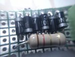
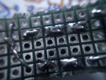
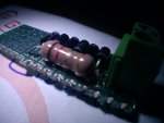
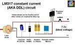
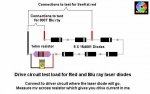
first I build the driver from "Laser Driver - It Can Be Done" and the test load from the same site... all exactly like them... see the pics below..
but I have a problem I can't measure the current right... I used different batteries/power supplies and I can't seem to figure it out...
here is the deal ...
with my first dummy load accross the resistor I get 0.00mV whatever I do I can't get a reading (in fact my driver is set to 420mA and with laser diode it works just right)
so I thought my dummy load was bad - I build another the only differences are that my silicone diodes are 1N4007 instead of 1N4001 which can withstand more voltage (could that be the reason ... I don't think so)...
so I made another test. I have a Short Open Can Red Laser Diode which has burnt out and turned into a LED but it still works as current drainer so I hooked it after a 1Ohm resistor and tested the current there... I get a reading of 160mV ??? but my driver is set to 420mA or even higher but I can't get that reading there...
I tested my driver at 4.5V, 6V, 7.5V and the difference is somewhere about 40-50mV but still not the proper reading....
can someone explain to me is my driver actually supplying that amount of current or is there something wrong with my readings/dummy loads....
as a proof of my driver being ok I can tell that when I hook up a Long Open Can Red Laser Diode and driver being set to 431mA it is working just fine ... ???? so confused....... pls help:bowdown::beer::wtf::wtf:


")