

- Joined
- Mar 29, 2013
- Messages
- 1,221
- Points
- 63
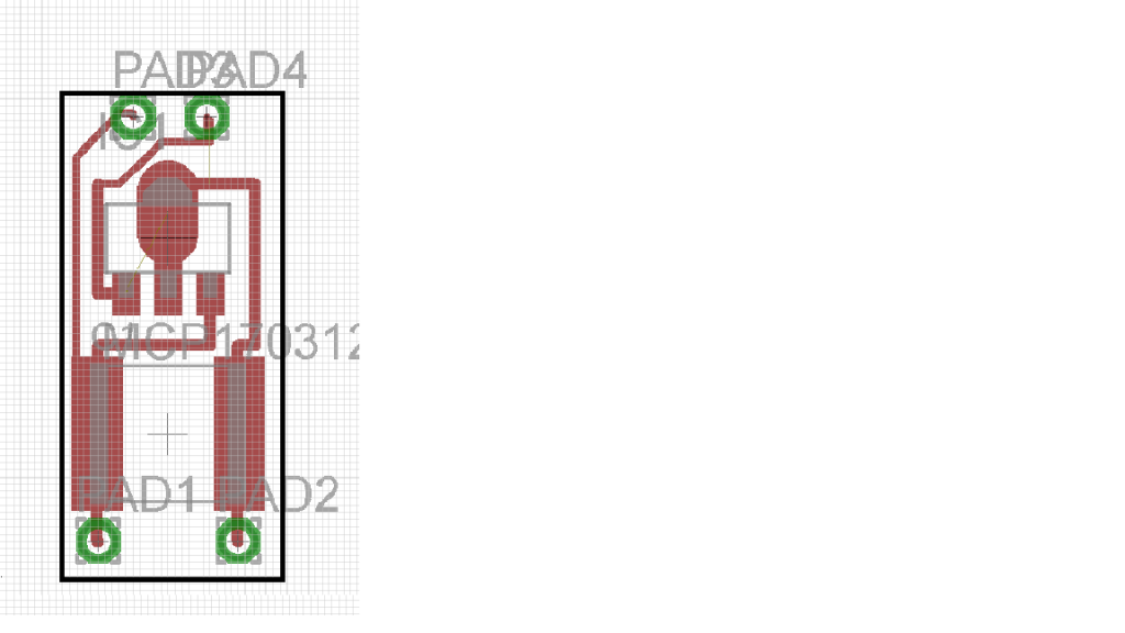
I have designed a board in EAGLE. Does this look alright?
The pads on the left side are Bat+ and LD+ (bottom & top respectively)
Pads on the right are Bat- and LD- (bottom and top respectively)
Thanks in advance!
-Matt
^^^ Question above still stands. That design all right? It uses a 0.1uf cap (big rectangle) and the AMC7135 chip.
About the size of a MOH linear driver. Maybe a bit smaller.
The only reason i used a large cap is cause my soldering sucks.
Want to get these ordered so i can order the rest of the parts.
:beer:
-Matt
Last edited:


