Welcome to Laser Pointer Forums - discuss green laser pointers, blue laser pointers, and all types of lasers

LPF Donation via Stripe | LPF Donation - Other Methods

Links below open in new window

ArcticMyst Security by Avery

Another boost driver thread

Joined
Apr 8, 2009
Messages
56
Points
0
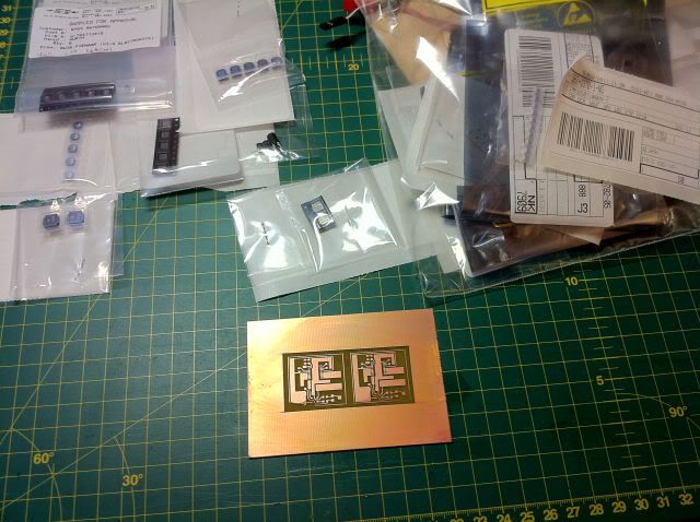
I set out to design and prototype a good single cell 445nm boost driver a while ago, because I have a need for it.

I have tried many designs and I'm having success with some of them.

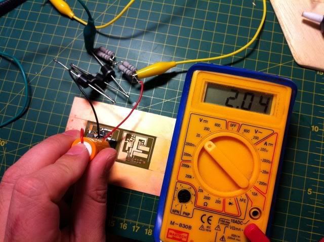
At the moment up to 2.4A @ 5.5V isn't a problem with an 18650. Even a good 18350 works. Running at 1.8A @ 4.8V I can achieve 82% efficiency.

All my boost circuits are continuous ground with high-side current sensing and current regulation.

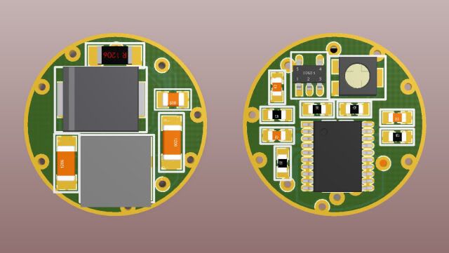
My main mission now is to buy the best components in the smallest size and shrink one of the drivers as small as possible. 16mm Round might be possible, but only when stacking PCBs.

Are there hosts that use a larger round driver?

I have contacts at an assembly house, and depending on pick&place costs I might do a production run in the future.

What other drivers do you guys think there might be a need for? I like designing and prototyping in my free time.
 

Attachments

  • IMG_4954c.JPG
    IMG_4954c.JPG
    105.3 KB · Views: 391


Blord

0
Joined
Dec 24, 2007
Messages
5,356
Points
0
It looks good. If you can make 2.4A@5.5V driver, how small can you make ?
 
Joined
Sep 12, 2007
Messages
9,399
Points
113
You won't get many buyers unless you can fit it in a cylinder with inner diameter of 10mm, and length 16mm, and have a <$25 price.
 
Joined
May 31, 2009
Messages
3,239
Points
63
The only problem I see is scaling and heat dissipation. Yes your larger components have good thermal capacity.. but when you get into micro SMD parts thermal affect will effect the preformance.

Good job though... If it's for personal use it looks good! But if your gonna manufacture it, it will need more work in terms of size, heat calculations etc...
 
Joined
Mar 29, 2011
Messages
1,056
Points
48
that's cool,

I am kinda ok with 16mm circular driver boards... even if there are 2pcb on top... but bigger ones are hard to find a host for...:thinking:
 

DTR

0
Joined
Jun 24, 2010
Messages
5,684
Points
113
Could you show us how the driver stays in regulation through the battery cycle on a Li-Ion and the current draw @ 1.8A.

Something like this.:beer:
 
Joined
Apr 8, 2009
Messages
56
Points
0
You won't get many buyers unless you can fit it in a cylinder with inner diameter of 10mm, and length 16mm, and have a <$25 price.

That looks like Aixiz dimensions. It will be hard getting a 1.8A driver in there...

I'm placing another component order today, so I should be able to make another revision later in the week.

At the moment none of the components generate significant heat. I hope to keep it that way when reducing the size.
 

Blord

0
Joined
Dec 24, 2007
Messages
5,356
Points
0
I think 12mm wide at significant lower price is good enough. Any LD that is running at 1.8Amp need a serieus big host to get rid of the generated heat, so the driver doesn't have to be that small.
 
Joined
Apr 8, 2009
Messages
56
Points
0
Good news. I've got parts on the way for another new design that runs at a higher frequency so the inductor (which takes up most of the space) will be significantly smaller. Efficiency should be >80% and the circuit will again be continuous ground with constant current regulation.
 
Joined
Apr 8, 2009
Messages
56
Points
0
After a few iterations I was able to fit and route all the components for another driver on a 17mm diameter round (Standard Chinese LED driver size) doublesided PCB.

The vias in the picture are oversized as I will be making prototypes myself and I don't have a 0.3mm drill bit.

Theoretically the design is sound and should be able to deliver 1.8A from a single Lithium cell.

No place was left on the board for a spring, but I will worry about that later...

Parts will arrive Monday/Tuesday.


17mmboost2.jpg
 
Last edited:
Joined
Apr 8, 2009
Messages
56
Points
0
Parts for the 17mm round 1.8A boost driver arrived.

I quickly made a single layer PCB for it as I don't want to waste time with the double sided one until I know it works well.

I'm going to solder it up now and I will let you guys know how it performs!

IMG_5038.jpg
 
Last edited:
Joined
Apr 8, 2009
Messages
56
Points
0
2A Out @ >5V !!

I used a 18350 cell in the photo. I'll tune the loop compensation circuit and check efficiency later. I will also get oscilloscope screenshots of everything that is important when the circuit is finalized. But for now I'm happy that it works with much smaller components than my other circuits.

IMG_5039-1.jpg
 
Last edited:
Joined
Mar 29, 2011
Messages
1,056
Points
48
great!!!!!!!!!!!!!!!!!!!! :drool::drool::pop::pop::pop: will the double-sided be around 17mm board? :) nice job!


Top