Welcome to Laser Pointer Forums - discuss green laser pointers, blue laser pointers, and all types of lasers

LPF Donation via Stripe | LPF Donation - Other Methods

Links below open in new window

ArcticMyst Security by Avery

Analog modulation with Flexmod P3

MadEye

0
Joined
Aug 6, 2011
Messages
129
Points
0
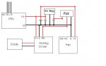
Ok, i thought you were using a 5V regulator. If using something like the LM317 you need to set it up in constant voltage mode using a resistor in a specific way. For setting it with a resistor you need a low tolerance resistor to be sure to get nice 5V, and not like 4.8 or 5.2... I feel like I told you this before. :)

I dont know exactly how you need to set it up, I will check the data sheet in a minute.

So using it you would only get 5% of output like that. Sure your Diode is really LEDd?


Joined
Jun 19, 2010
Messages
1,487
Points
63
AAAhh...sorry I misunderstood. I thought that the LM317 would work without the resistor but I guess I was thinking of the 5V regulator. My head is starting to swim :D

unfortunately the diode is dead....I un-hooked it from the driver and powered it up with my adjustable PSU and got no more lasing:mad:
 

MadEye

0
Joined
Aug 6, 2011
Messages
129
Points
0
Ok, this site explains it nice and even has a 5V sample... You could also use a pot and set the output with an DMM

KLICK

For applications like that setting up an LM317 is a lot useless work: You never need something else then 5V, you only need a few mA to uA... 100mA 5V regulators cost cents... I thought you got one when you "went down to radio shack and picked up some things"
 
Joined
Jun 19, 2010
Messages
1,487
Points
63
Thanks for the link....Your right it does seem to make much more sense to just use the 5V regulator.
I'll get down to the store tomorrow and try to find just the 5V regulator.
 
Joined
Jun 19, 2010
Messages
1,487
Points
63
Okay double post as an apology to MadEye.....I did read what you've been saying but I guess I didn't completely get my head around it.

I just ran down to the store and got the +5VDC Voltage Regulator 1amp(lucky seemed to be the last they had).
I plugged it into where I had the LM317 and got a nice 5V at the top and when I turned the pot it went down nicely to 0!

Thanks again for all the help. This is a very simple setup and should work great once I get another damm diode!;)
 

MadEye

0
Joined
Aug 6, 2011
Messages
129
Points
0
Nice to hear. Looks like you are not too far away from the next electronic store :D

1A is also a little bit wasted, but I also used an 1A on in my build - Because I had one here :>

Hope you get your new diode soon and everything works fine then. As long as you wait you can take a test load and make sure your driver is giving the right output, as well as check the linearity of your pot when connected to the driver... ;)

To encourage you a little bit: After building so many lasers without any major problem I killed 4 12x BR diodes in a row - The first 2 driver issue, and those 2 cursed me to be unable to harvest them any more -.-
 
Joined
Jun 19, 2010
Messages
1,487
Points
63
Thanks....
Those 12x BR's are even more expensive than the 445nm's. I'v only blew one other 445 and a couple of open can 660's but usually all my projects just miraculously work(I guess my electronics mojo is off today. I just trashed my 40W FAP I think trying to plug in a fiber to it:horse:........i'm not touching any more lasers today!)

EDIT: So I reset my flexmod. Turns out I had the high setting set WAY to high and I was reading it wrong with my DMM. I did some more reading on PL and found that most, and upon looking at mine the same, DMM's have a max mA for testing. Mine was 400mA which is why I was getting 0.0 when ever I tried to test and set the driver. Switching the Positive leg of the DMM to the unfused 10A max port solved the problem.
 
Last edited:
Joined
Jun 19, 2010
Messages
1,487
Points
63
I AM AT MY WITS END!!!

So I went digging through my stock and actually found another 445nm diode. I decided to build an "actually real" board for the modulation and put it into a "nice" housing. I also ran the fan to the PSU(this may or may not have been the NEW problem)

Okay, I got it all nice looking...believe it or not the modulation "board" did work perfectly when I tested it. I hooked up an on/off switch as well that worked just fine.
At first when I fired it up the driver went through its low power start up and then into the higher power setting(1.25A). Everything seemed fine but I didn't have any modulation change off the POT. After looking at it a bit closer I realized I didn't have a negative hooked up to the POT for the modulation. There happened to be an extra negative lead from one of my external hook ups that I could use so I soldered it to the POT.
Plugged the unit back in and switched it to ON. The driver cycled again and came to high power. I turned the pot and the power droped down to 0 and then turned it up again to full.
I turned it off and then turned it on again. I 'think' I may have heard a very small crack. There was no output from the laser and the red light on the driver was back on. A couple more try's and nothing....I clipped the wires to the diode and put it on the benchtop PSU and YUP....SURE ENOUGH....completely DEAD! not even an led.:cryyy:

I just don't know why this project has turned out to be such a huge problem but i'm setting it aside until I can really know what the hell is going on!
Here are some photo's of the build.

I'm Out for now!
IMAG0757.jpg


IMAG0759.jpg


IMAG0761.jpg


IMAG0766.jpg


IMAG0762.jpg


Believe it or not, this actually worked great when I tested it.
IMAG0764.jpg
 

MadEye

0
Joined
Aug 6, 2011
Messages
129
Points
0
first of all: I never used a flexmod before, but I assume its a good driver, and good driver will never kill your diode because of modulation mistakes. My analog driver (Isnt sold any more) had all kind of modulation protection and Im sure the flexmod has them too.

Second, it has probably nothing to do with your problem, but voltage regulators want small ceramic capacitors to work well. If you don't add them they start to pulse around their real output voltage and also can get warm. If you do your final build, please use them.

What is that black thing in your "control box"? Are you sure there is no general problem with your driver? When checking current, you also checked the voltage is in the range of 4-5V?

Since tomorrow is the last day before the world ends (Diablo returns :>) I could make a complete diagram how I wired my labby. But this only helps you if you can be 100% sure the flexmod is not your problem.

I would really just recommend you the driver I used, this was an Analog Only Driver made for projectors, and there was nothing to set... Just threshold and max current. It even has an onboard 0.5Ohm resistor to check the current by just connecting an single 1N400X diode... I really need to contact the manufacturer of this drive...
 
Joined
Jun 19, 2010
Messages
1,487
Points
63
Thanks MadEye for the reply. The black think is a 9V battery. I tried the control box with the 9V in testing and it seemed to respond just as well as with my wallwart. Zero to five volt with a smooth transition via the POT.

As for the driver, once I figured out that I needed the un-fused 10A port for testing, setting the driver by the instructions was very easy and I got all the readings that I expected. So all 'seems' okay with that.

My only guess, granted an un-educated one, is that the pull from the fan on the same PSU somehow interfered with the flow to the driver, but I would think that the driver would shut down. This is just a guess and perhaps not the best

I would think that there isn't any problem with my driver, instead with my build skills or some kind of cross connection that i'm not aware of.

I understand the end of the world is coming...I loved the first Diablo and played it for some time but haven't really checked out the new one.
I would appreciate the diagram when you get a chance and the driver your using seems pretty straight forward as well. I like to put photo's in my posts for others to search at a later date as they have helped me in my learning so much.:beer:
 

MadEye

0
Joined
Aug 6, 2011
Messages
129
Points
0
So, i tried do draw the simplest labby setup possible... In a final build you would of course add fuses, switches, maybe LEDs and everything you like.

I build my Labby with a 12V PSU, but the analog driver would need to drop about 7V with this at the diode current, which is a few watt of heat... So I added a 7V switching regulator to step down with high effieciency and the driver only needs to drop about 2V... Not necessary but it helps the driver a little bit to stay cold and you safe some Watts of Energy ;)

All crossing without a point have no connection! (Or at least shouldnt... :shhh:)

Ive build it basicly like that and it worked. So if you are sure you got that setup, I would assume you have a problem with your flexmod...

attachment.php
 

Attachments

  • labby setup.jpg
    labby setup.jpg
    19.6 KB · Views: 893
Joined
Jun 19, 2010
Messages
1,487
Points
63
3rd Time is the Charm!

Finally got it up and working on my 3rd diode. I checked the driver again and found it was outputting 3A!
So I went through the driver setting again.....and did it again for good measure.
I set the standby at 250mA and the high point at 1250mA. Everything seems to work. With the modulation turned all the way down I read around 2-3mW and on the high end 780-800mW(which seems low for 1.25A...perhaps it has something to do with the modulation?)
Anyways here is a very long video....you don't have to watch the whole thing, but it does match my LPM reading.
Thanks again all for your help. I hope that at some point in the future this thread will make it that much easier for others to do the same.:beer:

The leveling in the middle of the reading is mid point on the POT...then up to the high level for a bit and down to 2mW
445nmFlexmodmodulated.jpg


Joined
Mar 1, 2011
Messages
610
Points
0
So just a question from a casual observer...
Why are you using a second power source to operate your "analogue" modulation ?
Why aren't you just taking a split off the feed from the PSU ?
From the thread here it sounds like the first try you had a second transformer wired into your circuit for powering the variable voltage. From my experiences, connecting the grounds from different transformers into a common connection can lead to unreliable results. (I have had bad power oscilations in the outputs and have had the lower value transformer blow up on me.)
I think just tapping the higher power line out to drive your adjustment circuit would prove easier and simpler.
Just my thoughts for what they are worth.
 
Joined
Jun 19, 2010
Messages
1,487
Points
63
Simple answer: ....because I don't really know much about what I am doing. I didn't know if my main PSU could handle the modulation and/or my fan. I try to narrow what could be wrong with my builds through deduction. I don't have the background to know every part of my builds and try to piece it together through reading and experimentation.

The modulation running off a 9V battery I can live with, but do you think that I could hook up my fan to the same PSU that is feeding my driver/diode without any problems? With my last failures I decided to take the fan conneciton out of the mix to perhaps narrow down my problem.
 
Joined
Mar 1, 2011
Messages
610
Points
0
I can't say exactly what you can run on the PSU without the details of the PSU output.
Age, duty cycle, and a lot of other factors will also determine the output.
BUT the draw of the regulator circuit will be so small compared to the draw of the laser that there is not much of any chance that it will make a difference.

As far as the fan goes, that is a much different consideration.
Fans can cause a lot of other undesirable electrical effects on a circuit depending on many different things with the fan. With the potential for damage to the other components you need to be sure that your fan CAN'T cause problems before sharing the circuit. (Hook up a disconnected fan to something and use wind power to create electricity, albeit at a low level. Then think how changing the speed at which it is spinning while in a sensetive circuit can cause power changes.)


Top