LPF Donation via Stripe | LPF Donation - Other Methods
Links below open in new window
ArcticMyst Security by Avery


You are using an out of date browser. It may not display this or other websites correctly.
You should upgrade or use an alternative browser.
You should upgrade or use an alternative browser.
Analog modulation with Flexmod P3
- Thread starter 532 with Envy
- Start date


MadEye
0
- Joined
- Aug 6, 2011
- Messages
- 129
- Points
- 0
Normally you use 100nF on these.
And since you are using these on a PSU u should also add one to the input, as well as a bigger capacitor there... I think about 2200uF per Ampere is used in general.
In electric devices all GND (negative leads) are connected to each other. If you have for example a Computer PSU there could be something like 3 Ports: GND, +5V, +12V. All the voltage ports are meant +12V or +5V against GND. GND is always the zero reference... Or at least should be...")
So you can connect all the negative leads of your PSUs to each other and the driver and only have to put the Vin to Vin and 5V to modulation. When using different lab power supplies you should first check if all the negative leads are grounded. This should be most often the case, but some cheap ones have the positive lead grounded instead. I had a 24V power supply which did -24V to GND instead... (In some cases this can be wanted though)
And since you are using these on a PSU u should also add one to the input, as well as a bigger capacitor there... I think about 2200uF per Ampere is used in general.
In electric devices all GND (negative leads) are connected to each other. If you have for example a Computer PSU there could be something like 3 Ports: GND, +5V, +12V. All the voltage ports are meant +12V or +5V against GND. GND is always the zero reference... Or at least should be...
So you can connect all the negative leads of your PSUs to each other and the driver and only have to put the Vin to Vin and 5V to modulation. When using different lab power supplies you should first check if all the negative leads are grounded. This should be most often the case, but some cheap ones have the positive lead grounded instead. I had a 24V power supply which did -24V to GND instead... (In some cases this can be wanted though)
Last edited:
- Joined
- Jun 19, 2010
- Messages
- 1,487
- Points
- 63
So I should add a 100nF to the output of the 5V regulator and a 22,000uF capacitor on the input of the 5V capacitor?
MadEye
0
- Joined
- Aug 6, 2011
- Messages
- 129
- Points
- 0
The big capacitor is not directly for the input of the 5V regulator but for the whole PSU. And I dont think you use 10A out of it, so check how many Amps your final set up will drain and add 2200uF per A...
Also add one small 100nF capacitor to the input even though you already have the big one. The reason for this is electrolytic capacitors are slower and used to smooth out the ripple of the PSU while small ceramic capacitors are faster and can smooth out very very short drops which are to fast for an electrolytic capacitor. (Is there any short form for electrolytic capacitor in english?)
Also add one small 100nF capacitor to the input even though you already have the big one. The reason for this is electrolytic capacitors are slower and used to smooth out the ripple of the PSU while small ceramic capacitors are faster and can smooth out very very short drops which are to fast for an electrolytic capacitor. (Is there any short form for electrolytic capacitor in english?
)
Last edited:
- Joined
- Jun 19, 2010
- Messages
- 1,487
- Points
- 63
AAhh I see what you mean. Thanks for the explanation. So both are to even out the flow to the driver off the PSU and 5V regulator.
I'v got a couple of LM317's in stock, I would guess one of those should work with the 10K pot and a 100nF Cap on the output? I think i'm just about there with the controller box! Thank again for your help. I'v taken some pictures of my laser head and when I get the controller built and hooked up i'll take a video of the whole thing working hopefully!
I'v got a couple of LM317's in stock, I would guess one of those should work with the 10K pot and a 100nF Cap on the output? I think i'm just about there with the controller box! Thank again for your help. I'v taken some pictures of my laser head and when I get the controller built and hooked up i'll take a video of the whole thing working hopefully!
MadEye
0
- Joined
- Aug 6, 2011
- Messages
- 129
- Points
- 0
LM317 is fine if you use it in constant voltage mode, just be sure the resistor you are using for setting has a low tolarance so you get really close to exactly 5V.
You could also take a 5V 100mA regulator, these are in the same housing as those small transistors and not to expensive... These are giving a pretty precise output of 5v... I think +- a few mV...
A finished labby with with a pot for output is really nice, you can just test how visible for example 300mW are and all those things. I enjoy mine and am sure you also will like yours.
I also ordered an Flexmod now, even though I think it wont fit an arctic, but I was often thinking to use an analog driver to build a very precise constant current power supply since all of the affordable lab power supplys only show like 0.1A steps... So I think I will have some use for it
- Joined
- Jun 19, 2010
- Messages
- 1,487
- Points
- 63
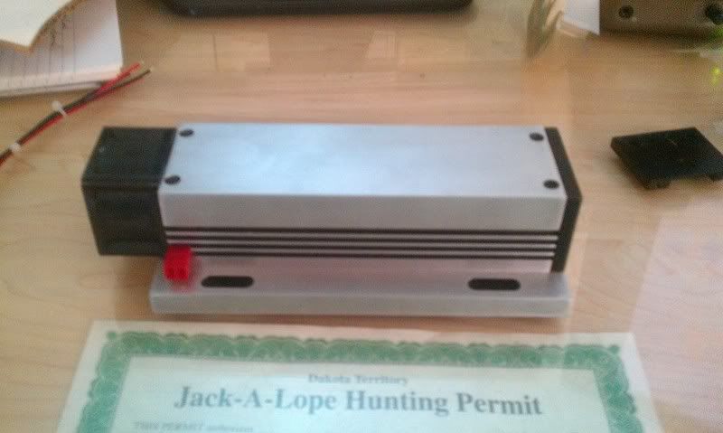
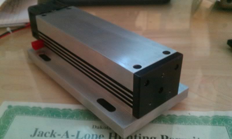
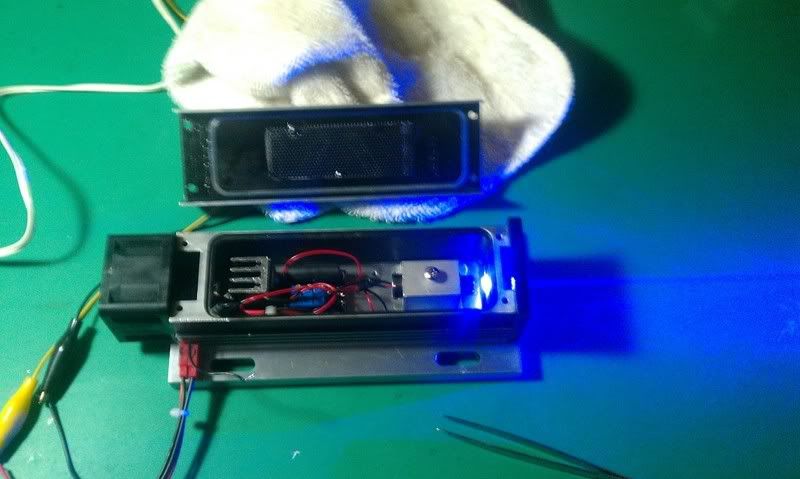
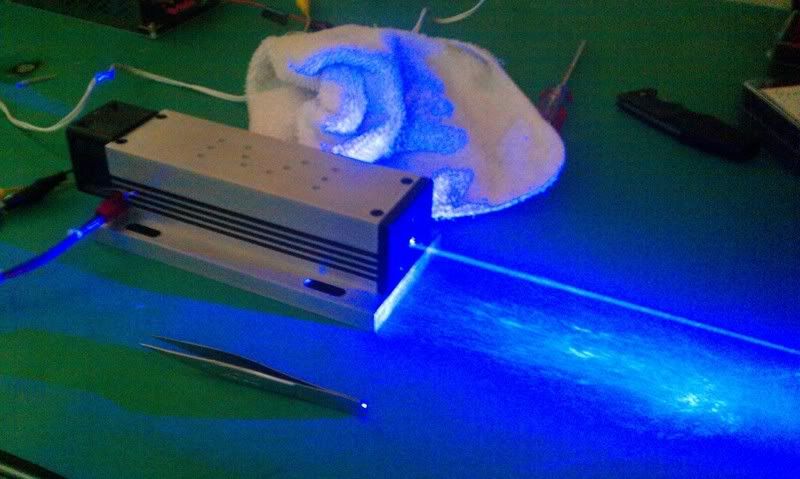
Welp here are some pictures of the laser head with the driver built in. The driver is running off a 12V 5A psu and the fan off a regulated walwart set at 6V 1A. The housing is the B&W tek ones that many may be familiar with, the fan came from the projector we are all familiar with.
When I get the control box all made up i'll post pictures of that as well.
Thanks all for your help and good luck in your own projects!
When I get the control box all made up i'll post pictures of that as well.
Thanks all for your help and good luck in your own projects!
- Joined
- Jun 19, 2010
- Messages
- 1,487
- Points
- 63
Okay so I went down to radio shack and picked up some things I was missing. I tried to make the controller but now seem to have some problems.
I couldn't find a 50k pot so i'm using a 5k(the only other I have is 100K). I hooked up the mod+ wire to the pot and then the 5v psu(regulated wallwart) to the positive and negative leads off my modulation set-up. Fired up the laser and got a lower level of light but no modulation from the POT. Now, even with the modulation set-up disconnected the laser seems to be at a lower level...it gives a quick flash when turned on and then drops down.(I hope I didn't blow this damm thing some how!!!!)
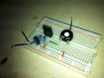
Anyways here is a picture of the mod set-up...I really thought this was going to be pretty straight forward but now i'm finding that it's really not(at least for me:yabbem
EDIT: So I don't know what the hell happened but I'v LED'd the diode! Everything was fine until I hooked up the modulator...Please take a look at the pictures above and tell me where I went wrong. This project will have to go on hold until I get another diode to hopefully NOT DESTROY!
I couldn't find a 50k pot so i'm using a 5k(the only other I have is 100K). I hooked up the mod+ wire to the pot and then the 5v psu(regulated wallwart) to the positive and negative leads off my modulation set-up. Fired up the laser and got a lower level of light but no modulation from the POT. Now, even with the modulation set-up disconnected the laser seems to be at a lower level...it gives a quick flash when turned on and then drops down.(I hope I didn't blow this damm thing some how!!!!)
Anyways here is a picture of the mod set-up...I really thought this was going to be pretty straight forward but now i'm finding that it's really not(at least for me:yabbem
EDIT: So I don't know what the hell happened but I'v LED'd the diode! Everything was fine until I hooked up the modulator...Please take a look at the pictures above and tell me where I went wrong. This project will have to go on hold until I get another diode to hopefully NOT DESTROY!
Last edited:
- Joined
- Sep 12, 2007
- Messages
- 9,399
- Points
- 113
I suspect leaving the mod input floating is a bad idea. Follow the directions in the manual - ground it while setting bias current, and apply 5V while setting the run current. Use an ammeter instead of a diode on the output while setting it up.
MadEye
0
- Joined
- Aug 6, 2011
- Messages
- 129
- Points
- 0
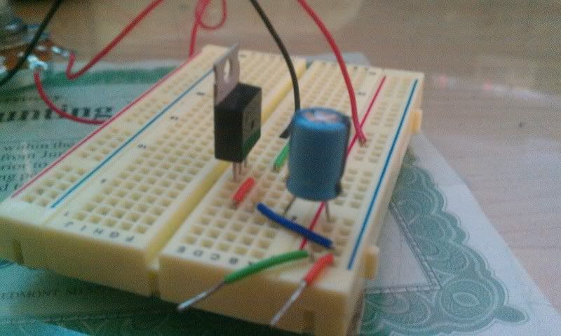
I cant see how the capacitor is connected, but somehow it looks like its in backwards Also its on the output and not on the input.
[edit:] wait... is this capacitor connected in series?
Also it looks like you changed the polarity of the breadboard, so negative is positive while postitive is negative. The ceramic capacitors are also missing, but thats not the problem now...
So did you measure the voltage before you applied it to the driver? like connecting a DMM and playing with the pot to see how it changes from 0 to 5V? Was everything correct? (Most DMMs could show some peaks when changing the pot postition, thats normal)
It should be impossible to kill a diode with modulation since the driver is never putting out more then 100%. You already tried it with 5V on the modulation input? Maybe you were overdriving your diode in general and it just survived this far.
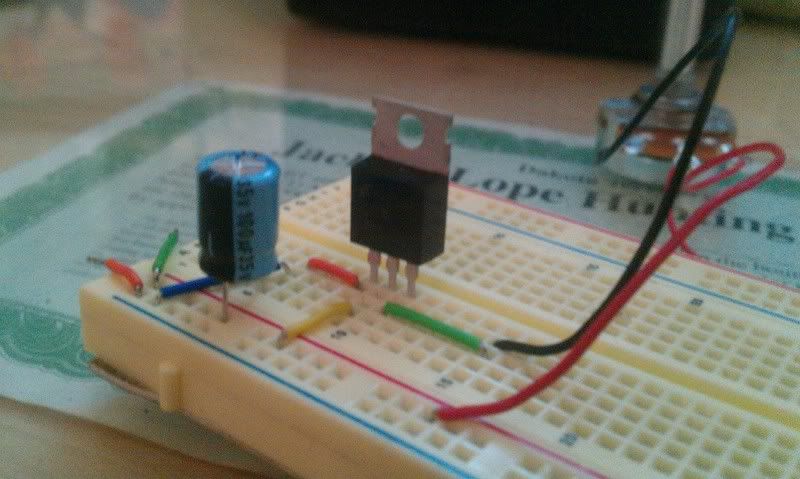
edit: Just made an quick setup, here is what it could look like:
Works fine, applied 12V to the input and got a clean 0-5V at the output...
When testing with the DMM the pot resistance is not critical. So also check how your voltage behaves when connecting the driver.

Also its on the output and not on the input.[edit:] wait... is this capacitor connected in series?
Also it looks like you changed the polarity of the breadboard, so negative is positive while postitive is negative. The ceramic capacitors are also missing, but thats not the problem now...
So did you measure the voltage before you applied it to the driver? like connecting a DMM and playing with the pot to see how it changes from 0 to 5V? Was everything correct? (Most DMMs could show some peaks when changing the pot postition, thats normal)
It should be impossible to kill a diode with modulation since the driver is never putting out more then 100%. You already tried it with 5V on the modulation input? Maybe you were overdriving your diode in general and it just survived this far.
edit: Just made an quick setup, here is what it could look like:
Works fine, applied 12V to the input and got a clean 0-5V at the output...
When testing with the DMM the pot resistance is not critical. So also check how your voltage behaves when connecting the driver.
Attachments
Last edited:
- Joined
- Jun 19, 2010
- Messages
- 1,487
- Points
- 63
@ Cyparagon: I think I may have set it incorrectly from the beginning. I did try to set it per the instructions before hooking up my diode, but don't think I did it right.
@ MadEye...thanks for the photo. My cap may be in backwards....i didn't think there was a difference. I also did have the - and + switched but plugged them in Like I should to the PSU(pretty sure....guess not)
I'll try it all over again...re-set my driver again.....I think that may be why I cooked the diode, perhaps it was set too high like MadEye said and I was just lucky to have it run as long as it did...then it got a spike of high amperage perhaps.....
LIVE AND LEARN I GUESS:banghead:
MadEye
0
- Joined
- Aug 6, 2011
- Messages
- 129
- Points
- 0
About electrolytic capacitors there is one very important fact: When they are backwards, they will explode. Its not they could explode, its really they WILL explode. When putting a 12V capacitor to 12V backwards this wont even need a long time to run. 36V on 12V will most often live longer, but they will not work properly when installed backwards. Its really worth a try if you have some you dont need, its cheaper then a firecracker But do it outside, they stink
When setting analog drives you should also remember how they work: They have a threshold current and a main current which will be added due modulation. When you set the 5V current to 500mA and then raise the threshold by 100mA, your current at 5V will also raise by 100mA to 600mA. So you have to set treshold first, and then the actual power with 5V. And after changing the treshold you also need to change the full current.
But when looking to your setup now it really looks like your cap really was in series. This should not work at all... So Im wondering how you LEDd your diode :thinking:
But do it outside, they stink When setting analog drives you should also remember how they work: They have a threshold current and a main current which will be added due modulation. When you set the 5V current to 500mA and then raise the threshold by 100mA, your current at 5V will also raise by 100mA to 600mA. So you have to set treshold first, and then the actual power with 5V. And after changing the treshold you also need to change the full current.
But when looking to your setup now it really looks like your cap really was in series. This should not work at all... So Im wondering how you LEDd your diode :thinking:
Last edited:
- Joined
- Sep 12, 2007
- Messages
- 9,399
- Points
- 113
Well, caps pass DC for a few milliseconds so that would explain the flash.
- Joined
- Jun 19, 2010
- Messages
- 1,487
- Points
- 63
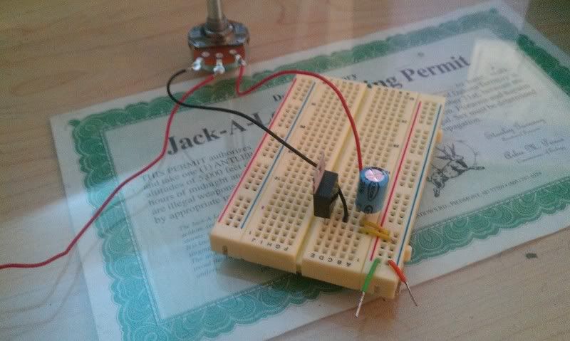
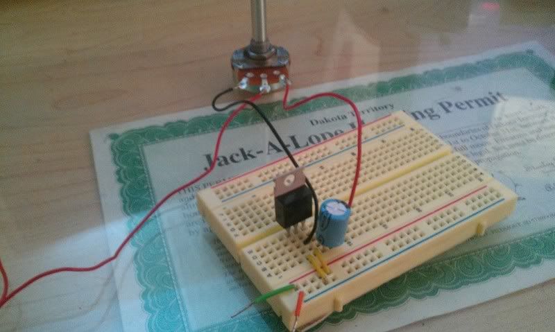
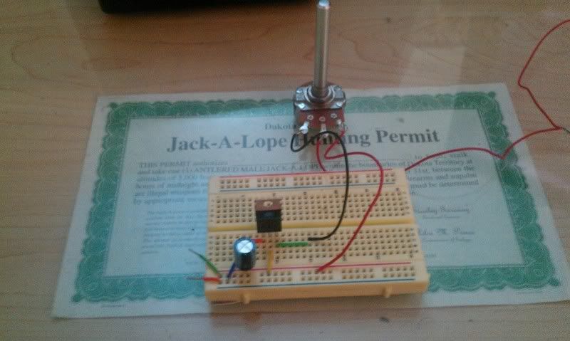
So thanks for the picture of your set-up MadEye...I did exactly what you did except for the small caps...hooked it up to a 12v supply and am getting Very strange readings. First time I tried it myself I got nothing, then I did it just like yours and it 'seems' to work...kind of.....
I get Zero at one end of the pot! That's a good start. At the high end though it seems to only go up to 250mV? The DMM shows it going up steady and seemingly evenly but stops at the 250mV mark for some reason.
I must have the cap in correctly because I haven't seen any smoke or explosions...yet.
Here are some more pictures.
Thank you all for your limitless patience with my inexperience!:beer::beer:
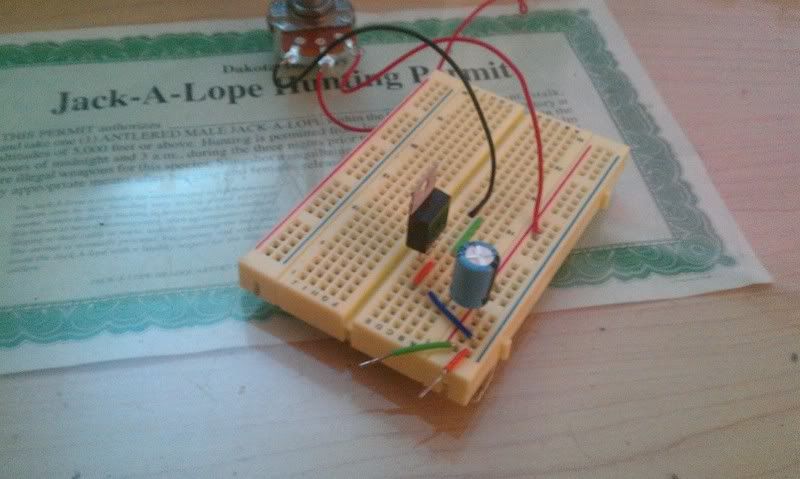
And yes if anyone is wondering I am a Mighty Jack-A-Lope Hunter and that IS my permit to do so!!

I get Zero at one end of the pot! That's a good start. At the high end though it seems to only go up to 250mV? The DMM shows it going up steady and seemingly evenly but stops at the 250mV mark for some reason.
I must have the cap in correctly because I haven't seen any smoke or explosions...yet.
Here are some more pictures.
Thank you all for your limitless patience with my inexperience!:beer::beer:
And yes if anyone is wondering I am a Mighty Jack-A-Lope Hunter and that IS my permit to do so!!
MadEye
0
- Joined
- Aug 6, 2011
- Messages
- 129
- Points
- 0
What do you get when measuring directly the output of your regulator? Maybe you have some special pot? measure if it really goes down to zero.
What regulator do you use? Just what is written on the housing.
What regulator do you use? Just what is written on the housing.
Last edited:
- Joined
- Jun 19, 2010
- Messages
- 1,487
- Points
- 63
When I put the DMM on the LM317 I get 11.95V when I touch both DMM points to it and I get 240mV when I put the positive on the LM317 and the negative to the negative lead. The pot i'm using is a 5k-Ohm linear-taper potentiometer....the cap is 100uF electrolytic capacitor.
