Welcome to Laser Pointer Forums - discuss green laser pointers, blue laser pointers, and all types of lasers

LPF Donation via Stripe | LPF Donation - Other Methods

Links below open in new window

ArcticMyst Security by Avery

Analog (external pot) based PWM Driver - Does this look right?

rhd

0
Joined
Dec 7, 2010
Messages
8,475
Points
0
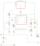
Although I've added externally adjustable current to drivers before, I'd like to do dimming the "right way" and add externally adjustable PWM.

So, assuming I already have the driver that can take a PWM input, does the design I've put together below look like a valid way to create a ~3.9 khz PWM signal that will vary from 5% to 100% duty cycle based on the position of a 5k pot?

  1. Is there a simpler way? (I guess a 555?)
  2. Is there a cheaper way? (The approach below requires a $4 IC, plus a second IC to regulate its input voltage to 5V)
  3. Does anyone think 3.9 khz is the wrong frequency to pulse at?

attachment.php
 

Attachments

  • PWM driver.png
    PWM driver.png
    12.1 KB · Views: 475
Last edited:


Hiemal

0
Joined
Dec 27, 2011
Messages
1,443
Points
63
A simpler way would probably be to use a 555 timer but the problem with that is you have to add a few more components than just the standard 555 timer schematic otherwise you'll be limited to only above 50% duty cycle.


555-duty-cycle.gif


This modification does achieve a wider range but it's still only between 35% and 75%...


3.9 khz is probably a little low, honestly, and since it's in the audio spectrum i'd probably go a little higher, like 20-30 khz. Duty cycle is the primary thing that changes the brightness, obviously so realistically you could choose any arbitrary frequency and it'd be fine (as long as whatever driver you're using can support it)

Instead of using the external IC to regulate to 5 volts you might be able to get away with using a 5.1 volt zener diode regulator instead, which should be cheaper since an oscillator shouldn't draw very much current.
 
Last edited:
Joined
Dec 11, 2011
Messages
4,364
Points
83
RHD; I've used that exact IC before and it all looks good to me. In fact, I'm quite a fan of the LTC699X series of chips. I have big plans for the LTC6990 actually, but to my immense displeasure they only come in SOT-23 SIZE!!!!! I had to special order break-out boards and I was barely able to solder the damned things in place. I only ordered two of each of the LTC699X series chips and I busted both one-shots and then reused the break out boards for my two 6990 oscillators currently sitting in my breadboard. I still have one used 6992, and one unused one left but I refuse to blow $5 by trying to solder SOT-23's with a 1/16 iron tip and 22ga solder.

The PWM frequency depends on application. At 700Hz (a common flashlight dimming frequency) you can still detect the pulsing by eye with a fast movement of the light source or quickly turning your vision. I generally used 2.5KHz for my own personal dimming projects, so there's no reason ~4KHz would be a problem.

As Quack pointed out a 555 is very limited in terms of duty cycle, roughly 52-94%. You can get around this by a complicated method of switching the signal path to an inverting buffer after the 555 when ~55% duty is reached and then ramping the 555 duty back up towards ~94%. It's not really a "linear feeling" descent at all since you have to activate a switch half way through the range.

I say stick with the LTC chip as long as you can solder it. I thought the damn things were SOT-223's when I ordered mine.
 

phenol

0
Joined
Oct 30, 2007
Messages
533
Points
18
74HC123 can do the job and it's a cheap jellybean part...use the TI application note for inspiration


Top