

Hi everybody,
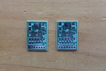
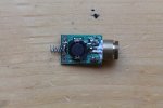
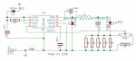
I recently built and tested a custom driver based on the A6211 driver from Allegro. It is designed to provide a maximum of 2.5A of current to the laser diode. In my case, I am using an Osram PL TB450B blue laser diode at 1.5A - the maximum recommended datasheet value - and everything functions very well. The current regulation is stable and the laser diode works fine.
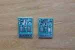
The driver uses up to five 1206 resistors to measure the current flow and has a schottky diode protecting the electronics from accidental reverse polarity. The source voltage should be larger than 6V. The practical bottleneck for the maximum voltage value is the voltage limit of C3. The 12V marking on the board is a conservative estimation which targets 16V capacitors. At the moment, I am using a 25V capacitor C3. The A6211 driver itself can go up to 48V. On the whole, I obtained best results with 3-4 protected Li-Ion batteries (types 18650 or 16340).
On the markings of the board, I specified a very conservative maximum current of 2A, so that there is some margin for fault tolerance and experimentation. The board has a trimmer pot which is used to tweak the current after the components have been soldered on. The resistor values specified in the schematic allow a current between 1A and 2.22A depending on the position of the trimmer pot.
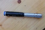
As a host/body for the laser diode, I used one from a cheap laser from China. The schematic diagram and the BOM of the board are attached.
The board is designed for hand soldering. It is manufactured locally in Bulgaria (EU). If you wish to know more about the board or you want to experiment with it and get a board or a development kit, drop me a note anytime.
I recently built and tested a custom driver based on the A6211 driver from Allegro. It is designed to provide a maximum of 2.5A of current to the laser diode. In my case, I am using an Osram PL TB450B blue laser diode at 1.5A - the maximum recommended datasheet value - and everything functions very well. The current regulation is stable and the laser diode works fine.
The driver uses up to five 1206 resistors to measure the current flow and has a schottky diode protecting the electronics from accidental reverse polarity. The source voltage should be larger than 6V. The practical bottleneck for the maximum voltage value is the voltage limit of C3. The 12V marking on the board is a conservative estimation which targets 16V capacitors. At the moment, I am using a 25V capacitor C3. The A6211 driver itself can go up to 48V. On the whole, I obtained best results with 3-4 protected Li-Ion batteries (types 18650 or 16340).
On the markings of the board, I specified a very conservative maximum current of 2A, so that there is some margin for fault tolerance and experimentation. The board has a trimmer pot which is used to tweak the current after the components have been soldered on. The resistor values specified in the schematic allow a current between 1A and 2.22A depending on the position of the trimmer pot.
As a host/body for the laser diode, I used one from a cheap laser from China. The schematic diagram and the BOM of the board are attached.
The board is designed for hand soldering. It is manufactured locally in Bulgaria (EU). If you wish to know more about the board or you want to experiment with it and get a board or a development kit, drop me a note anytime.
Attachments
Last edited:


