- Joined
- Aug 7, 2010
- Messages
- 2,086
- Points
- 0
@dzrick
Just a second. Where are you located at? (asking because I saw the attachments names...)
Just a second. Where are you located at? (asking because I saw the attachments names...)


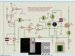
First, the voltage source connected to the gate is bypassing the regulation of the op amp and turning
the FET on hard. That will blow everything up - FET, diode, everything. Remove it completely.
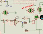
Then all you need is a single 10Ω resistor between the FET's gate and the op amp. No ground
connection here, either
First, the voltage source connected to the gate...
all you need is a single 10Ω resistor between the FET's gate and the op amp. No ground
connection here, either
")

 ) Anyway, before I buy those, I'll use what I have. Only yesterday I've realized that I only need 10, about 5 per transistor (since I'm using 2), wich will drag about 22 amps each..! Once again, thanks! !