Welcome to Laser Pointer Forums - discuss green laser pointers, blue laser pointers, and all types of lasers

LPF Donation via Stripe | LPF Donation - Other Methods

Links below open in new window

ArcticMyst Security by Avery

808nm 300mW driver help?

Joined
Feb 8, 2011
Messages
3
Points
0
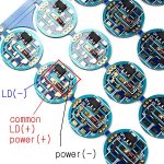
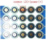
So, I bought 3 of these:

Code:
Wavelength : 808±10nm
Power Output : CW 300mW
Working Current(mA) : ≤400mA
Working Voltage(V) : 2.2V
Working Temperature ( ℃ ):-10~+40
Threshold Current (mA):≤120
Beam Divergence (deg): Θ// :17 . Θ⊥38 .
Sealed Size : TO18(5.6mm)
Life span : >10000 hours

Now Im wondering, what should I drive 'em with. IMO, I need both voltage and current regulators.. since I dont have any 2.2 volt batteries around :D
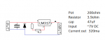
Best I've seen is those LM317 drivers, but they can regulate only either voltage or current (rright?), so I'd need something to do them both.

Help is requested


Ps. Im new to lazors but I know something about electronics
Pss. I know about the hazards of powerful IR-lasers etc.


rhd

0
Joined
Dec 7, 2010
Messages
8,475
Points
0
I think an LM317, setup to regulate current, is enough. The voltage will work by voodoo magic :)

We use the same LM317 current regulating circuit for 3V reds, and 4.5V + blues. So I don't know why a 2.2V IR wouldn't work too.
 

anselm

0
Joined
Nov 22, 2010
Messages
2,448
Points
0
The voltage will work by voodoo magic
:crackup:
Funny, yet correct!
As long as the input voltage to the whole thing is >= Diodes Vf+3V....

What are going to do with an highly dangerous, invisible and thus mostly useless IR laser anyway, if I might ask?
 
Joined
Feb 8, 2011
Messages
3
Points
0
What are going to do with an highly dangerous, invisible and thus mostly useless IR laser anyway, if I might ask?

Well.. to put it out short: highly dangerous, invisible and thus mostly useless stuff - ofcourse ;)
Whadd'ya thought?

Edit.
I found some current calculator tool and made an regulator with it (see attachment). Now my question: will this schematic work or shall I use another one? Also, which one?

Edit v2.
Im pretty positive this schematic will work. However, what sould I use as a dummy load, since I dont have any diodes free? Also, will this blow my LD?
 

Attachments

  • driver.png
    driver.png
    9.2 KB · Views: 3,186

anselm

0
Joined
Nov 22, 2010
Messages
2,448
Points
0
That circuit looks fine to me.
As a dummy load you should make one like everybody else here uses one.
I'm sure you find a schematic of it real quick. Otherwise google "it can be done".

Remember that the 200ohm potentiometer is funny little bastard.
At first, in the 200 to 20 Ohm range, nothing much will happen.
And then suddenly there's a lot of change in current in the last 10 degrees you turn.

To make sure though the current stays at a safe level all the time, you really should
measure it using said dummy-load.;)
 

Used

0
Joined
Feb 15, 2011
Messages
11
Points
0
Why do you put a resistor and the pot? resistance used for?
 
Joined
Jan 14, 2011
Messages
424
Points
0
The resistor is used to set maximum current so you don't (inadvertantly) blow the 317 regulator with too low a setting on the pot. Go to alldatasheet.com or some other datasheet source, look up the LM317 datasheet, and see the example of the current regulator/source application. You will find the Current formula for this configuration (Vref/R= Iout). I use Texas Instruments LM317T (DCY's in SMD package) which publish Vref as 1.2 volts. National and most others post as 1.25V. If you plug it all anto an Excel spreadsheet, you'll see that at R= .1 Ohm, Iout= approx. 12A, just a little over the rated max capacity of the 317. At R= 0.8 Ohm, Iout = 1.5A. At 1.2 Ohm, 1.0A, then as you go to, say 100 Ohm, you get down to 12mA. You have to measure the uninstalled end resistance ot the pot, but you can assume zero ohms to be safe and that equals melted LM317, so you put a fixed resistance in the path to insure your R value never goes below, say 0.8 Ohms, so the highest output setting you could possiblly get is 1.5A. (If you do the spreadsheet, you can tweek for your own safe max value, much below the rated max of the 317 you choose to use) same principle works for all linear shunt regulators (117 family, 780x's, ect.) used as constant current sources.
Ditto what Anselm said, so use a ten turn trimmer, or at least a linear taper, rather than a single turn (270 degree) audio taper pot.
 
Last edited:

SHIN

0
Joined
Jul 25, 2009
Messages
207
Points
18
Hi. shantec.

Welcome to the forum.

Try a amc7135 board with single Li-ion battery.
It is negative-regulator, and there is no host insulation problem with IR LD.
Because case pin of IR LD is positive.

One of amc7135 can permit 350mA.
There are many source for simple amc7135 board. One is:

$16.68 - Quality AMC7135 350mA Regulated Circuit Board for DIY Flashlights 20-Pack - Flashlight Parts and Tools

Previously I built 808nm 300mW with 1x amc7135, and 500mW with 2x amc7135.
I cut the board like the following pictures then LD pin soldered at both side of the board.
Amc7135 board can be containable in Aixiz.

Although board cutting is not recommenadable for a starter, this is interesting method for small IR LD module.

SHIN
 

Attachments

  • sku_3160_front.JPG
    sku_3160_front.JPG
    103.9 KB · Views: 1,010
  • sku_3160_back.JPG
    sku_3160_back.JPG
    84.7 KB · Views: 482
Last edited:


Top