Welcome to Laser Pointer Forums - discuss green laser pointers, blue laser pointers, and all types of lasers

LPF Donation via Stripe | LPF Donation - Other Methods

Links below open in new window

ArcticMyst Security by Avery

5 mode attiny control circuit for Benboost

Joined
Apr 5, 2010
Messages
196
Points
0
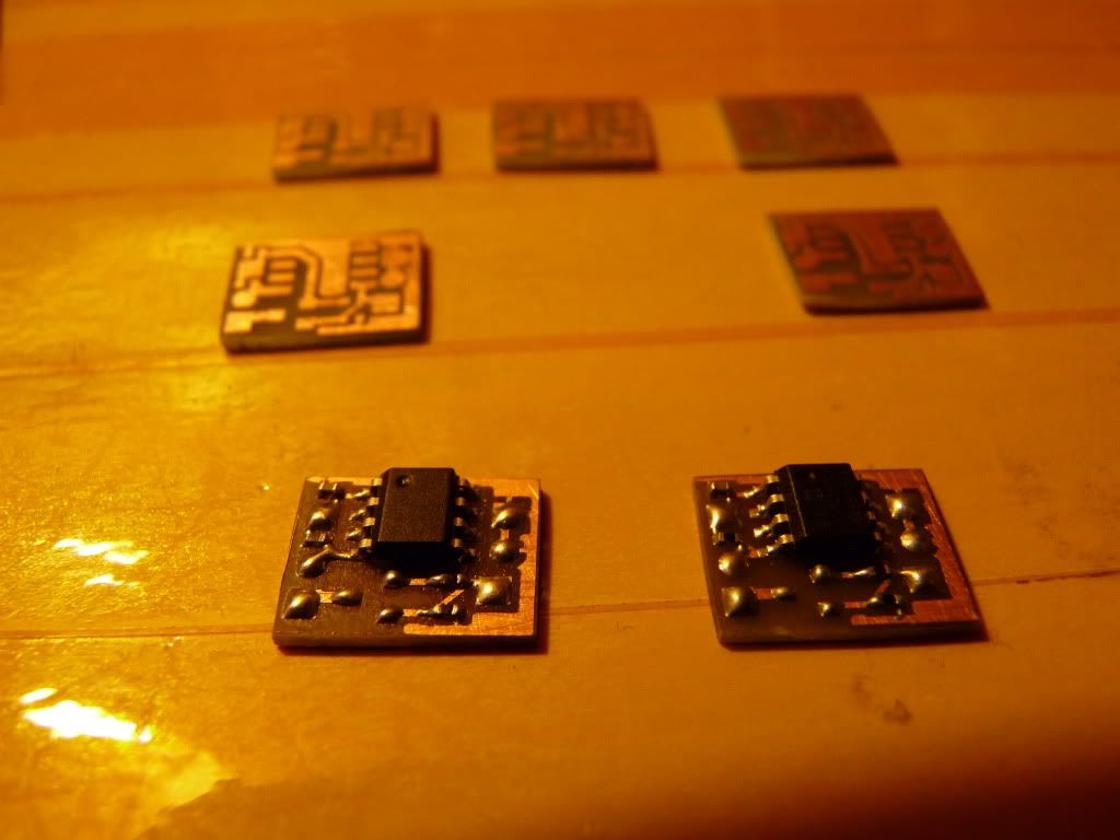
I reverse engineer the design in most flashlight's brightness control part of the driver. I isolate the PWM and microcontroller part of the circuit and hook it up to BenBoost or other similar driver runs with PWM. The board is tiny!! And the code for Attiny13 can be find on budget light forum. I program this to be 5-mode, low-mid-high-strobe-SOS with mode memory. It fits into Aixiz with BenBoost, It's a tight fit, but it fits. the whole board is 7mm tall.

IMG_0317.jpg


IMG_0319.jpg


IMG_0323.jpg


IMG_0328.jpg


Here is a video!!


Joined
Apr 5, 2010
Messages
196
Points
0
Update schematic as RHD requested!!
The diode is for reverse protection, optional.
ad19b577.jpg
 

rhd

0
Joined
Dec 7, 2010
Messages
8,475
Points
0
This is really neat.

eBay has some attiny programmers that work with the SOIC8 chips. I've also noticed in general that you can get SOT-23-6 to DIP adapters, that would presumably then work with an attiny DIP programmer.

This is definitely a project I want to try out :)

Update schematic as RHD requested!!
The diode is for reverse protection, optional.
ad19b577.jpg

Thanks!

Which code on BLF did you use ?
 
Last edited:
Joined
Apr 5, 2010
Messages
196
Points
0
My friend told me that he found the code on there, I didn't have the time to mess with programming yet. Too busy at school. I assume you can search "flashlight with perfect mode"
 
Joined
Apr 5, 2010
Messages
196
Points
0
Here is another schematic reverse engineer from AK-47 7135 driver. This one can choose from 3 different settings by shorting out TP1, TP2, TP3 with ground. this will set the mircocontroller into Low-high, low-mid-hi-strobe-sos, or low-high-slow stobe.
56f0ab29.jpg
 
Joined
Mar 29, 2011
Messages
1,056
Points
48
damn, there goes my idea :wtf: ..... at least I am using PIC microcontroller, few external components, and I do the coding myself MUAHAHAHA :D :na::na: I can do modes whatever you need and you can regulate the brightness from 1 to 100% with an external button :D

P1060373-1.jpg
:D
 
Last edited:
Joined
Apr 5, 2010
Messages
196
Points
0
I just look at the C file of the code!! It's not as hard as I thought!! Hopefully, I'll figure it out at the end of the week!!
 

chefla

0
Joined
Mar 24, 2011
Messages
169
Points
18
You don't need R1/R3 in the schematic in post#2. It is a voltage divider for the ADC. You could however use that for Vin measurement. Vin>3 Volt: driver turns on - Vin<=3.0V: driver does not turn on. And don't forget the integrated EEPROM. E.g. use it to save the last mode (or don't). Just a few ideas...
 
Last edited:


Top