LPF Donation via Stripe | LPF Donation - Other Methods
Links below open in new window
ArcticMyst Security by Avery


You are using an out of date browser. It may not display this or other websites correctly.
You should upgrade or use an alternative browser.
You should upgrade or use an alternative browser.
2vdc 300-400ma schematic needed
- Thread starter krawczuk
- Start date


- Joined
- Sep 12, 2007
- Messages
- 9,399
- Points
- 113
How's'aboot a wall wart with a voltage regulator?
How's'aboot a wall wart with a voltage regulator?
well, thats what i was thinking.. BUT i need the actual schematic , with current and voltage regulation ..
i`ve sifted thru a few but they are 3v or over and have NO current regulation.
mark
GBD
0
- Joined
- Oct 25, 2010
- Messages
- 783
- Points
- 0
For current regulation,
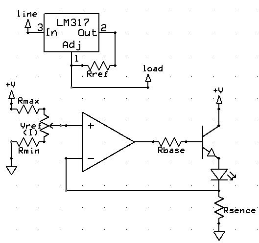
since you only require 300-400ma, then the simplest you can go is an LM317 in line setup as a current regulator, the first drawing. Also, search for the LM317's datasheet, this device can be used either as a current or a voltage regulator, so simplest I guess is to use 2 of them, one for each regulation respectivly.
If you require more current, you can build a bigger version of the LM317, a current source. this requires a higher part count though, also, if you do intend to pushing more current with the current source, replace the transistor there with a darlington pair.
Also note that the LM317 has a decent voltage drop, so your supply will need to be higher then 2VDC.
Since you are on a laser forum, I assume you are driving a laser diode, so build a test load first (search around here to see how) and use that to simulate a laser diode when you setup your supply.
Hope that clears it up.
Last edited:
- Joined
- Sep 12, 2007
- Messages
- 9,399
- Points
- 113
i need the actual schematic , with current and voltage regulation ..
I don't think you can have both at the same time. The load will either be 2V, OR 300mA. What do you plan to run with it? If it is for a laser diode, you need constant current.
123splat
0
- Joined
- Jan 14, 2011
- Messages
- 424
- Points
- 0
Solution is simple using the popular LM317. Go to AllDatasheet.com or some other data sheet site (Natoional Semiconductor or ON Semiconductor, ect.) locate and download the data sheet. Look in the 'Typical Applications'. You want the basic voltage regulator (it will tell you how to calculate the Resistor value in the 'Adjust' leg. Or, use the '1.2V-20V Regulatop with Minimum Program Current' example and set for 2Vdc (use a much smaller R2). Good idea to include small cap on the input (0.1uF), but you do not need the large one on the output side for battery supply (it's in the doc, read the data sheet). Also keep the input voltage reasonablly low (6 Vdc in, as example, NOT 12 or 24 Vdc) as that will keep your heat dissapation on the regulator IC down. Then run the output from the regulated voltage in to a Constant Current Regulator (LM317 configured as a "Precision Current Limiter", this is what most of the build it yourself guys on this forum seem to use for driver circuits), again, the formula to calculate the resistance for your selected current is in the docs. Works like a charm. I've been using this confiiguration with shunt regulators like the 117 family (includes the LM317) for about twenty years without problem.
