Welcome to Laser Pointer Forums - discuss green laser pointers, blue laser pointers, and all types of lasers

LPF Donation via Stripe | LPF Donation - Other Methods

Links below open in new window

ArcticMyst Security by Avery

17mm buck-boost driver (TPS63020 and LT6106)


Joined
Mar 18, 2012
Messages
173
Points
0
This is quite possibly a good replacement for the Flex. Unfortunately, it still doesn't solve the >5.5V in or 5.5Vout problem that the Flex has too. Means they can't run 12x diodes.

There is a simple solution for this problem... if you put a battery at the output of the driver and in series with the load, you solve the problem because the driver output voltage adds itself to the battery voltage (you must connect the negative of the battery to the driver output and the positive to the diode).
If you simulate this situation with tina-ti you will find that you can drive a test-load of 12 silicon diodes.
You will have a two-batteries buck-boost driver with extended output range and also with relaxed driver operation.
This solution could be, more generally, applicable to any driver and a battery that can sustain the output current flow through itself
 
Last edited:
Joined
Dec 27, 2011
Messages
2,062
Points
48
The major limit is the 40°C rise current (2.5A). You should expect this inductor become (very) hot when the output is at 1.8A but you can try it...

Ok, how about this one?

PCMC053T-1R5MN Susumu | 408-1371-1-ND | DigiKey

Inductance 1.5µH

Current 6A
Current - Saturation 10A
Current - Temperature Rise -

Tolerance ±20%
Shielding Unshielded
DC Resistance (DCR) 20 mOhm Max

Applications General Purpose

Package / Case 0.205" L x 0.185" W x 0.118" H (5.20mm x 4.70mm x 3.00mm)
 
Joined
Jan 14, 2011
Messages
3,816
Points
63
Interesting, luke. Mind throwing up a schematic? I think I am getting what you are saying, but not sure.
 

Hiemal

0
Joined
Dec 27, 2011
Messages
1,443
Points
63
There is a simple solution for this problem... if you put a battery at the output of the driver and in series with the load, you solve the problem because the driver output voltage adds itself to the battery voltage (you must connect the negative of the battery to the driver output and the positive to the diode).
If you simulate this situation with tina-ti you will find that you can drive a test-load of 12 silicon diodes.
You will have a two-batteries buck-boost driver with extended output range and also with relaxed driver operation.
This solution could be, more generally, applicable to any driver and a battery that can sustain the output current flow through itself

This is dangerous. You're essentially putting the laser diode at the mercy of whatever the second battery wishes to put out.

I wouldn't recommend doing this at all.
 
Joined
Mar 18, 2012
Messages
173
Points
0
Ok, how about this one?

PCMC053T-1R5MN Susumu | 408-1371-1-ND | DigiKey

Inductance 1.5µH

Current 6A
Current - Saturation 10A
Current - Temperature Rise -

Tolerance ±20%
Shielding Unshielded
DC Resistance (DCR) 20 mOhm Max

Applications General Purpose

Package / Case 0.205" L x 0.185" W x 0.118" H (5.20mm x 4.70mm x 3.00mm)

Parameters are ok (40°C rise current of 6A is lower than coilcraft but it should go), lenght (5.2mm) is ok, width (4.7mm) is somewhat big but it should go... nice inductor
 
Joined
Mar 18, 2012
Messages
173
Points
0
Interesting, luke. Mind throwing up a schematic? I think I am getting what you are saying, but not sure.

attachment.php


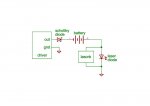
This is the schematic.
The schottky diode protects the driver against reverse current flow and the lasorb protects the laser diode against overcurrents and spikes at power-on power-off.
To make a test with a given driver i would suggest to use a test load and to check the currents values and waveforms at all conditions (power-off, power-on and operational).
 

Attachments

  • sch.jpg
    sch.jpg
    53.6 KB · Views: 919
Joined
Jan 14, 2011
Messages
3,816
Points
63
You sure that would work? What if the IC has a different Vcc vs. Vin pin? One for IC power, the other for inductor power?
 
Joined
Mar 18, 2012
Messages
173
Points
0
You sure that would work? What if the IC has a different Vcc vs. Vin pin? One for IC power, the other for inductor power?

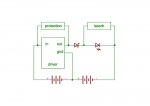
If you look at any battery charger schematic you will find two protection diodes, one in series at the output and another between the output and the input of the regulator (in parallel with the regulator...). This is done to control the currents directions (block the flow) and so the polarities when the regulator is powered off.
Every driver has a given schematic and so you must carefully consider the polarities (voltage differences) before adopting this connection.
For example a buck driver has an input voltage greater than output voltage, a boost driver the inverse and so you can choose the protection diode direction.

edit: to analyze the schematic and simplify your considerations you can move the battery after the laser diode (connect the battery negative to the diode cathode and the battery positive to ground, for the functionality consideration this is equivalent to the previous schematic).
Also you can test this configuration simply by using a dual output power supply

attachment.php
 

Attachments

  • sch1.jpg
    sch1.jpg
    53 KB · Views: 745
Last edited:
Joined
Dec 27, 2011
Messages
2,062
Points
48
Driver 3A single Li-ion

Saw this on another forum. Dunno, dude hasn't gotten much attention besides me. Looks pretty decent, though. Maybe this wheel has already been invented.

A few thoughts...

A. It is not open source. So you are buying from him.
B. How much is he charging?
C. What kind of availability?
D. It is a flashlight driver I think, so it may be designed for a far more robust diode and it may not have spike limiting for more sensitive laser diodes.
 
Last edited:
Joined
Dec 29, 2009
Messages
3,136
Points
63
Ah, had my threads mixed up. Thought there was a different thread for an open source driver.

So how do you choose an inductor for this bad boy? match inductance, make sure saturation rating is higher than what is needed, and make sure 40*C rise in temp. is at a suitably high current value?
 
Joined
Dec 27, 2011
Messages
2,062
Points
48
Ah, had my threads mixed up. Thought there was a different thread for an open source driver.

So how do you choose an inductor for this bad boy? match inductance, make sure saturation rating is higher than what is needed, and make sure 40*C rise in temp. is at a suitably high current value?

And the hard parts, it has to fit on the very small landing pad and be available. Coilcraft makes a very good, reasonably priced, low DCR 1.5uH inductor that would be great - except they don't let anyone else sell it and they aren't in stock right now.


Top