

foulmist
0
- Joined
- Mar 29, 2011
- Messages
- 1,056
- Points
- 48
I received the 2 boards from Kent. One with a blown TPS and the other had the TPS a little bit not properly soldered.  anyway I fixed them and tested them... Here are some results (mostly in videos but I will try to explain what is happening in them).
One thing that needs to be changed in the layout is the Zener diode.. It's messing the ouput a lot causing all kinds of oscillations at different voltage input and output ranges. And some spikes even. After removing it the output is almost perfect. Only few problems arise at output current less than 250mA causing some oscillations and in buck mode at maximum current and input voltage of 5.5V. But those are rare cases that I think no one here will ever meet.
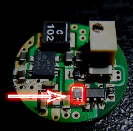
First video is showing the tests with the original design featuring the 5.6V (~5.3V) Zener diode which is considered to be for OVP (overvoltage protection) BUT it's absolutely not necessary as the TPS already features a built-in one at ~6.8V. It caused a lot of problems at the output.
Second video is showing tests with the zener diode removed. Also I tried a A123 3.6V LiFePo4 Battery which is Ok for currents upto 1.6A but in order to meet the full output ~1.9A to ~2.1A a 3000mAh 3.7V Li-Ion battery was used.
Ripple Current in boost mode at maximum output is almost 60mA which is pretty good!!! It lowers with decreasing the output current.

Ripple Current in buck mode is almost 20mA. Awesome!

I didn't take a shot at the startup but there aren't any spikes at all.
Only with the zener the startup was oscillating a bit before it stablelized (how the hell is that word spelled)
Ok I will try to explain with bubbles in the videos: here goes...
Video with Zener:
Video without Zener:
Thanks for watching.
My Overall opinion is this driver (without the zener) is pretty good (and expensive ). With the common ground and pot for adjusting the current it beats all the drivers til now.
Great job Luke. The force is strong with you :wave:
anyway I fixed them and tested them... Here are some results (mostly in videos but I will try to explain what is happening in them).One thing that needs to be changed in the layout is the Zener diode.. It's messing the ouput a lot causing all kinds of oscillations at different voltage input and output ranges. And some spikes even. After removing it the output is almost perfect. Only few problems arise at output current less than 250mA causing some oscillations and in buck mode at maximum current and input voltage of 5.5V. But those are rare cases that I think no one here will ever meet.
First video is showing the tests with the original design featuring the 5.6V (~5.3V) Zener diode which is considered to be for OVP (overvoltage protection) BUT it's absolutely not necessary as the TPS already features a built-in one at ~6.8V. It caused a lot of problems at the output.
Second video is showing tests with the zener diode removed. Also I tried a A123 3.6V LiFePo4 Battery which is Ok for currents upto 1.6A but in order to meet the full output ~1.9A to ~2.1A a 3000mAh 3.7V Li-Ion battery was used.
Ripple Current in boost mode at maximum output is almost 60mA which is pretty good!!! It lowers with decreasing the output current.
Ripple Current in buck mode is almost 20mA. Awesome!
I didn't take a shot at the startup but there aren't any spikes at all.
Only with the zener the startup was oscillating a bit before it stablelized (how the hell is that word spelled
)Ok I will try to explain with bubbles in the videos: here goes...
Video with Zener:
Video without Zener:
Thanks for watching.
My Overall opinion is this driver (without the zener) is pretty good (and expensive
). With the common ground and pot for adjusting the current it beats all the drivers til now. Great job Luke. The force is strong with you
:wave:
Last edited:


