Welcome to Laser Pointer Forums - discuss green laser pointers, blue laser pointers, and all types of lasers

LPF Donation via Stripe | LPF Donation - Other Methods

Links below open in new window

ArcticMyst Security by Avery

17mm buck-boost driver (TPS63020 and LT6106)

Joined
Mar 29, 2011
Messages
1,056
Points
48
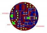
the other side of the cap is ground . - you can see the vias points connecting the bottom side. I am pretty sure I have sent you the correct wiring pads.

the diode you have has a dirty window or a dirty lens ;)
 
Last edited:


Joined
Mar 18, 2012
Messages
173
Points
0
Here is the wirings
-Luke

attachment.php
 

Attachments

  • layout.jpg
    layout.jpg
    130.4 KB · Views: 752
Joined
Dec 29, 2009
Messages
3,136
Points
63
Try cleaning first. It's less destructive.

Also, nice reflow work ;) The videos always make it look so easy, but I always have a hard time controlling the components. You might want to take some rubbing alcohol and a soft static free brush to the top of that board to get rid of some of those stray solder balls.
 
Joined
Feb 7, 2012
Messages
977
Points
0
Thanks I actually fell asleep in my chair last night.. lmao.. Going to regret that...

I finally have a day I can take off so I will get some testing going today. I still dont have a scope so cant go too to far with it.

I think I am starting to understand the schematic better.. :)
 
Last edited:

AnthoT

0
Joined
Jan 14, 2012
Messages
2,133
Points
48
Thanks I actually fell asleep in my chair last night.. lmao.. Going to regret that...

I finally have a day I can take off so I will get some testing going today. I still dont have a scope so cant go too to far with it.

I think I am starting to understand the schematic better.. :)
If you need any help with the scematic there are many here to help :)
 
Joined
Feb 7, 2012
Messages
977
Points
0
Well I must have not had that IC on correctly Or I did something else wacky.. I hooked it up to testload and the current was reading 388ma on 6diodes so I started adjusting the pot and nothing seemed to change So I am sure I did something. Then I started thinking Buck and I made the fatal error of trying 2 18650's serial. Poof of smoke dead IC then remmbering the FMT driver was 5.8Vmax I am assuming this IC is the same or similar. Arghh the hard errors we make. Going to make another tonight. Hopefully 2nd time is the charm.
 
Joined
Mar 29, 2011
Messages
1,056
Points
48
Well I must have not had that IC on correctly Or I did something else wacky.. I hooked it up to testload and the current was reading 388ma on 6diodes so I started adjusting the pot and nothing seemed to change So I am sure I did something. Then I started thinking Buck and I made the fatal error of trying 2 18650's serial. Poof of smoke dead IC then remmbering the FMT driver was 5.8Vmax I am assuming this IC is the same or similar. Arghh the hard errors we make. Going to make another tonight. Hopefully 2nd time is the charm.

I think you should try 3 or 4 diodes at first and

I think the IC was soldered correctly, otherwise you won't be able to get any current at all at the output.

Yes you should use only one battery with it. 6V is the max!

if the output doesn't change with the pot, check if the pot is soldered correctly in fact double check all components.

if you continue to experience the same problem, further testings must be made - scope and such.

EDIT: also try using the PSU at first see what current it is drawing. Set it at 3.7V and allow for maximum current. Is your battery capable of high current draw? What battery did you use?
 
Last edited:
Joined
Feb 7, 2012
Messages
977
Points
0
Well I built the second board I had parts for and I tried to use less solder paste it all looked good when I hooked it up I didnt get any current at all. but it and my lead wires got quite hot quite fast. So I dont know where I went wrong.

Tom if you want me to send you the drivers I built to take a look at I would appreciate it + if you get one working or both you will at leist be able to test them out I know the IC is fried on the first one. Big black volcano in the center of it.

All my 18650's are 10A continuous current draw. Samsung, sony and AR's. I will never buy a trustfire or the like again wasted too much $$$ on them.
 
Joined
Feb 7, 2012
Messages
977
Points
0
I still have inductors and boards for 2 more but need to get more parts.. I'm not giving up yet! I just thaught having someone more experienced take a look at them... Tiny lil buggers to work on. :)
 

AnthoT

0
Joined
Jan 14, 2012
Messages
2,133
Points
48
I still have inductors and boards for 2 more but need to get more parts.. I'm not giving up yet! I just thaught having someone more experienced take a look at them... Tiny lil buggers to work on. :)

Yup those are close leads, you did great just not bridging them :gj:
Good thing I include more boards I guess :D
 
Joined
Feb 7, 2012
Messages
977
Points
0
yep! I appreciate it. I still gota pat my back considering I baught my first solder iron about 6months ago and the only thing I have reflowed b4 was the ben boosts which are alot easier to do than this. Eh we try we learn! I'm sure I will get it after a couple more tries..
 
Joined
May 25, 2010
Messages
3,655
Points
0
My Best Guess is Your Bottom Center Heatsink Pad is shorting with over flow solder on one or more pins/legs.

When reflowing these kind of chips one of the main issues is that. It is very common to happen. It happens to me all the time on my boost driver. But lucky its very easy to Rework and Fix.:D

The best thing to do is Remove the chip Clean and wick up all the old solder. Then apply new solder paste and add a little flux on the bottom of the chip before you put it back on the board to get Reworked.
 
Last edited:
Joined
Mar 29, 2011
Messages
1,056
Points
48
Sure Kent,

I have some spare TPS ICs so I will put a working one and reflow the whole board and lets hope I get it to work.

If I do I will put it on the scope too. :) and post all the results here.
 
Last edited:


Top