Welcome to Laser Pointer Forums - discuss green laser pointers, blue laser pointers, and all types of lasers

LPF Donation via Stripe | LPF Donation - Other Methods

Links below open in new window

ArcticMyst Security by Avery

10A Driver with Modulation , First attempt

Joined
Jan 14, 2009
Messages
1,452
Points
83
Hey ,

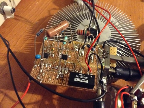
Well after a while I decided to try and make a variable constant current source with modulation for diode testing

The circuit if partly from a PFD form analogue devices .

The basis setup is 2 op-amps one being used to drive the mosfet and the second is the current sense and feedback .

With a gain of 20 and a voltage present on the first opamp non inverting input of 5 volts the sense resistor is 20/5V to give 250mV across the resistor , then that is selected for that drop and the max current you want .

In my build it did drift above this as with a 0.03 Ohm resistor I get 10A at 5.4V , i'm not to sure why as with a 0.03 ohm sense I was aiming for 8.3A max .

0.250mV/0.03Ohm = 8.33333333333A , 0.250mV*20 Gain = 5V

Second thing I noticed is even at 250mV drop over the sense resistor it gets untouchably hot even though its a 5W resistor dissipating 4W worst case

The circuit runs from a 5V to +/-12V DC-DC converter .

I wanted to ask as there are people on here with a lot more driver experience do these scope outputs look ok to you ? the load is two 150A diodes with drop of 1.65V each but as this is the first driver i've ever done past a LM317 I wanted to see what others thought before I risk a laser diode .

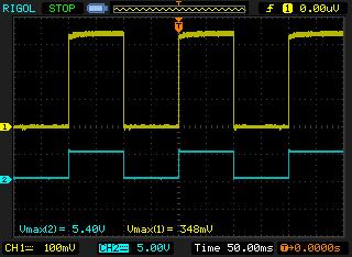
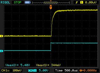
Supply is 5 volts and in the test the driver was driven with a 10Hz square wave but in my final design a voltage divider will be used to set the current of the diode and then on and off with 5 volts from a small DC-DC converter .

Both shots are at 10Hz , 0 - 11A Current ( 10A ? ) , there is ripple at about 20mV - 30mV , Blue trace is modulation and yellow is voltage across the sense resistor .


NewFile3 by TwirlyWhirly555, on Flickr

NewFile4 by TwirlyWhirly555, on Flickr

IMG_0721[1] by TwirlyWhirly555, on Flickr
 
Last edited:


djQUAN

0
Joined
May 27, 2013
Messages
1,154
Points
63
Re: Dual AD8610 10A Driver , Modulation , First attempt

Where is the schematic?
 

djQUAN

0
Joined
May 27, 2013
Messages
1,154
Points
63
Re: Dual AD8610 10A Driver , Modulation , First attempt

Why did you put the load in between the mosfet and shunt? Did you try putting it between positive supply and mosfet drain (LK2 in schematic)?

I'm not sure why there should be a 10M positive feedback as it is supposed to operate in linear region. Positive feedback is used to add hysteresis to make oscillators. Try removing it and see if the ripple disappears. The long leads might also cause oscillation. Can you measure the frequency of the ripple?

Also check your return currents and see if there might be voltage differences causing an error on the feedback voltage resulting to the actual being higher than calculated.
 
Joined
Jan 14, 2009
Messages
1,452
Points
83
Re: Dual AD8610 10A Driver , Modulation , First attempt

Thanks , No real reason just placed it there as it was how I ended up laying it out , I just tried the load at mosfet drain and the current range went to 0-22A so something is wrong . The modulation is set at 5 volts so there should be 8.3A and 250mV across the resistor but this doesn't seem to follow what's happening at all .

Removing the 10M reduces the ripple by a tiny amount I will try and measure the ripple with and without it .

Grounding on the output side of the DC-DC converter to input ground gives nasty 300Khz oscillations , I think to eliminate power supply issues I will use 2 9V PP3 battery's to make a +-9V supply and then a Lipo cell for the low voltage supply

I will draw up a circuit with the added supply in soon and check currents .
 
Last edited:

djQUAN

0
Joined
May 27, 2013
Messages
1,154
Points
63
Re: Dual AD8610 10A Driver , Modulation , First attempt

If you can post hi res photos at different angles of your breadboard wiring, we might be able to spot connection mistakes if there are any.
 
Joined
Aug 14, 2013
Messages
2,655
Points
63
Re: Dual AD8610 10A Driver , Modulation , First attempt

Those traces look good. How did you get
the transients out of the waveform on your
Rigol? I had to disable longmem on mine.
 

djQUAN

0
Joined
May 27, 2013
Messages
1,154
Points
63
Re: Dual AD8610 10A Driver , Modulation , First attempt

I just use default settings on mine. I don't use the long memory unless I need to zoom in pretty close in a waveform. What transients are you having problems with?
 
Joined
Aug 14, 2013
Messages
2,655
Points
63
Re: Dual AD8610 10A Driver , Modulation , First attempt

The Rigols have a noise problem. On mine it
shows up in longmem mode in the low mV
ranges.
 

djQUAN

0
Joined
May 27, 2013
Messages
1,154
Points
63
Re: Dual AD8610 10A Driver , Modulation , First attempt

I don't expect mine to be the best in noise performance. Besides, mine's the entry level DS1052E bought years ago :)

Which model do you have? Digital scopes will appear to be noisy due to the way they work. Not sure, but this might be of help if you have not seen these.


Joined
Aug 14, 2013
Messages
2,655
Points
63
Re: Dual AD8610 10A Driver , Modulation , First attempt

It's a DS1102E. Those videos are pretty
helpful. I've seen them before. It's a
little different from that, though. There
are spikes that occur regularly in time
with the triggering. There were some
discussions about it I remember reading
when I was testing drivers a few months
ago. The only solution seemed to be taking
it out of longmem mode.
 

djQUAN

0
Joined
May 27, 2013
Messages
1,154
Points
63
Re: Dual AD8610 10A Driver , Modulation , First attempt

I don't really use the longmem mode on mine so I probably don't experience the problem you're encountering. Sorry I won't be of much help on that :(

Only thing I can think of is that longmem mode has higher sample points? so the scope can see the spikes that are usually ignored in normal memory mode. Where it is coming from, I'm not sure. Possibly something to do with the input stage but I'm probably wrong on that one :p
 
Joined
Aug 14, 2013
Messages
2,655
Points
63
Re: Dual AD8610 10A Driver , Modulation , First attempt

Yeah, I'm stumped as well. The only things
that work are taking it out of longmem
mode, a low pass filter, or just cropping
it out. Thanks for trying anyway.
 

djQUAN

0
Joined
May 27, 2013
Messages
1,154
Points
63
Re: Dual AD8610 10A Driver , Modulation , First attempt

If that's the case, then it could be as simple as a noisy input stage. I'll see what I find when I toy with mine on longmem mode.
 
Joined
Jan 14, 2009
Messages
1,452
Points
83
Re: Dual AD8610 10A Driver , Modulation , First attempt

Well I have replaced the supply with a -+ 12V supply from 6 Lipo cells and used a 3.7V source for the low voltage ,

The oscillations are at 400Khz and are present on the mosfet gate as well as across sense resistor I will get a picture of it , things look to have got worse than when I started the thread .

Ill try and find the issue but if not then I will go for a pre made driver .
 
Last edited:

djQUAN

0
Joined
May 27, 2013
Messages
1,154
Points
63
what's the peak to peak voltage of the oscillations at the various points it is present?

You can try temporarily using a large value gate resistor to slow down the mosfet and hopefully stabilize the loop.

I think the breadboard layout is partly to blame. The op amps are high speed at 50V/us and can oscillate with the right circumstances. You can also try using slower op amps on the initial design just to rule this out.


Top