Plan B
0
- Joined
- Jan 7, 2011
- Messages
- 131
- Points
- 0
Hi all,
I need a hand with simple lighting toy I'm trying to build. It seems it should be a simple problem, but I can't seem to wrap my head around how to wire it up. I need to pack 9 rgb LEDs as close as I can to each other in a 3x3 pattern. These are 4 lead, common cathode LEDs and it makes for tight wiring so I would like to keep it simple and use as few connections and resistors as possible.
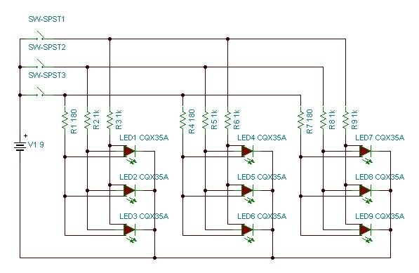
My original plan was to take 3 LEDs in a row and solder their common leads together, red to red, cathode to cathode and then solder on 1 resistor for each channel. (This would give me 3 LEDs running in parallel?) After building 2 more of the above, I was planning to solder together all the common channel leads and cathodes and wire them to there respective switches and battery. (This gives me 9 LEDs running in parallel?) Here's what the circuit looks like.

I set it up on a breadboard and started messing with the red. I used a 9v battery and three 180ohm, 1/4W resistors, 1 for each bank of 3 LEDs. The red on these LEDs has a fv of 1.8v and run at 20mA. This set up didn't work and only the first bank of 3 LEDs lit up. This makes no sense to me since the other banks were connected to the same switch and negative line as the first bank. Why would the first bank work but not the second and third? Another thing was the resistor on the working bank got very hot, very fast so I think I'll have to replace it with two 360ohm resistors in parallel as 1/4w's are all I have.
Anyways, if someone could help me figure out what's wrong with my circuit or suggest a better set up I would really appreciate it.
Cheers,
Plan
I need a hand with simple lighting toy I'm trying to build. It seems it should be a simple problem, but I can't seem to wrap my head around how to wire it up. I need to pack 9 rgb LEDs as close as I can to each other in a 3x3 pattern. These are 4 lead, common cathode LEDs and it makes for tight wiring so I would like to keep it simple and use as few connections and resistors as possible.
My original plan was to take 3 LEDs in a row and solder their common leads together, red to red, cathode to cathode and then solder on 1 resistor for each channel. (This would give me 3 LEDs running in parallel?) After building 2 more of the above, I was planning to solder together all the common channel leads and cathodes and wire them to there respective switches and battery. (This gives me 9 LEDs running in parallel?) Here's what the circuit looks like.
I set it up on a breadboard and started messing with the red. I used a 9v battery and three 180ohm, 1/4W resistors, 1 for each bank of 3 LEDs. The red on these LEDs has a fv of 1.8v and run at 20mA. This set up didn't work and only the first bank of 3 LEDs lit up. This makes no sense to me since the other banks were connected to the same switch and negative line as the first bank. Why would the first bank work but not the second and third? Another thing was the resistor on the working bank got very hot, very fast so I think I'll have to replace it with two 360ohm resistors in parallel as 1/4w's are all I have.
Anyways, if someone could help me figure out what's wrong with my circuit or suggest a better set up I would really appreciate it.
Cheers,
Plan
Last edited: