

Jufran88
0
- Joined
- Feb 9, 2011
- Messages
- 578
- Points
- 0
I had a lot of time to think about this build since some of the parts have been laying around my room since summer, heh. Here's a few shortened specs since I know paragraphs can be a bit of a stretch for some people 
- CREE XM-L 6500k - 7000k U2 bin from DX *link*
- 3D LED Maglite (Black Friday sale @ Lowe's for $15!)
- Sandwiched AMC 7135 1050mA drivers x 3 for total of 3150mA output
- 1 mode: high
- Powered by 3 D alkaline cells
- Huge heat sink made by Jayrob!
- Dremeled stock reflector to fit
The CREE XM-L U2 bin is the highest and brightest, supposedly there is a U3 bin, but I haven't encountered any yet. It claims a 320 Lumen/W efficacy vs the common T6 at 300 Lumen/W (both driven at 100% @ 700mA). The fact that it came from DX can be sketchy, but I'll just have to take their word for it.
Flashlight pics:
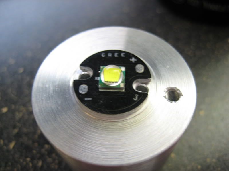
I first Thermally epoxied the LED star on the heat sink made by jayrob, awesome job BTW! I let it cure overnight while I worked on the other components:
Removed the diodes and replaced with a jumper wire to bridge the connection:
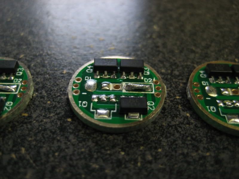
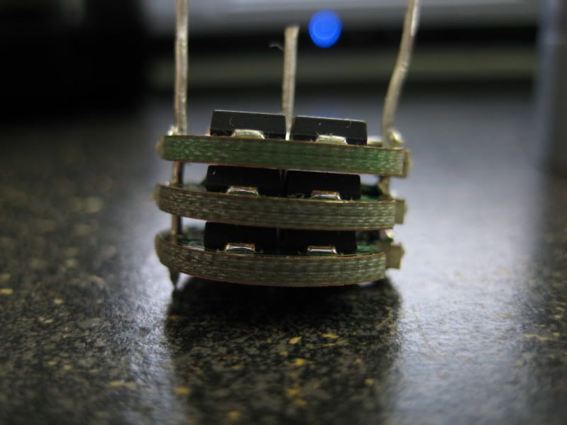
I sandwiched them together and broke off a section to isolate the LED - of the driver for easier connection. The extra wire sticking out will be cut off:
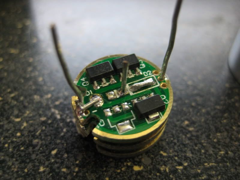
Sandwiched driver should be outputting 3.15A given the right amount of voltage since it is a linear driver:
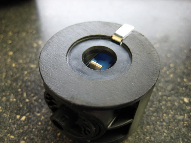
Switch prep using a Torx T8:
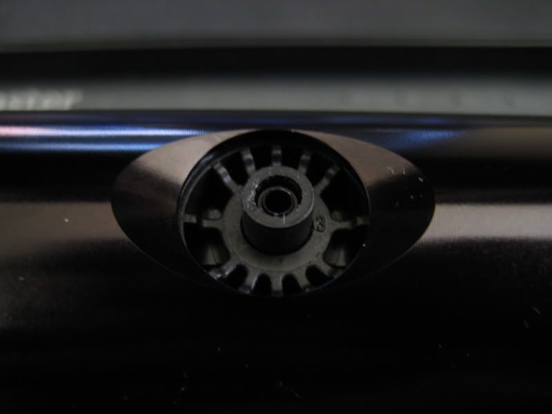
Dremeled the stock holder and sanded:
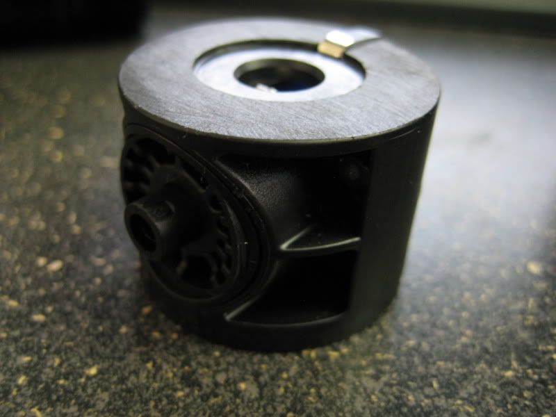
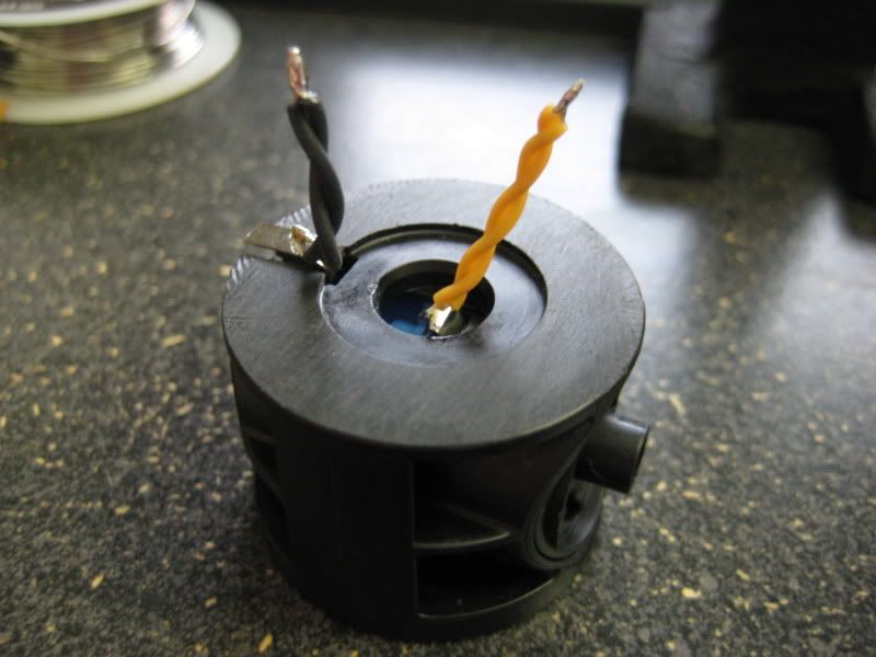
Added a twisted pair of silicone wire where it will connect to the driver:
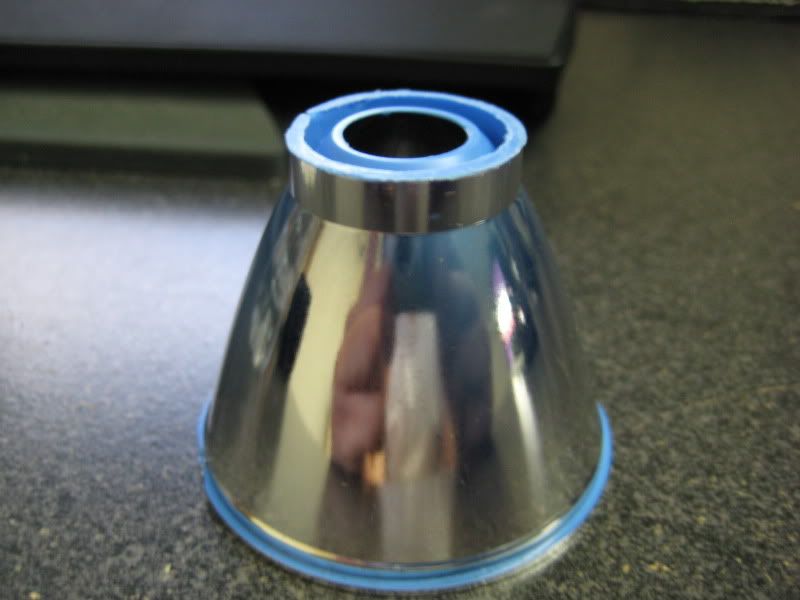
Dremeled and sanded the stock reflector to fit the base of the mounted LED:
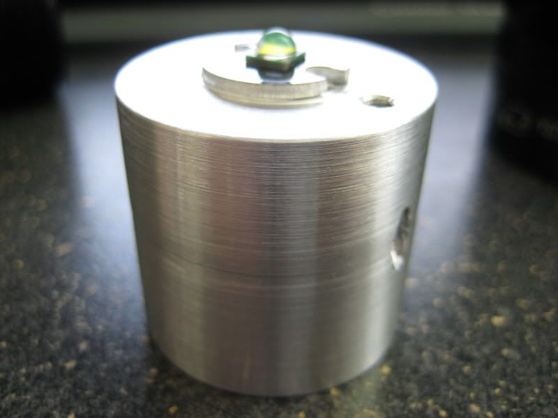
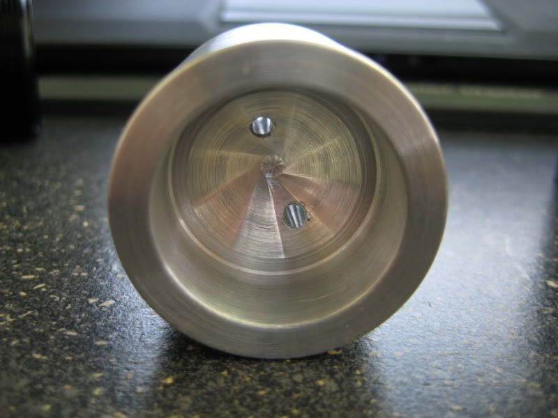
Connected the driver to the LED and set it down and screwed in set screw:
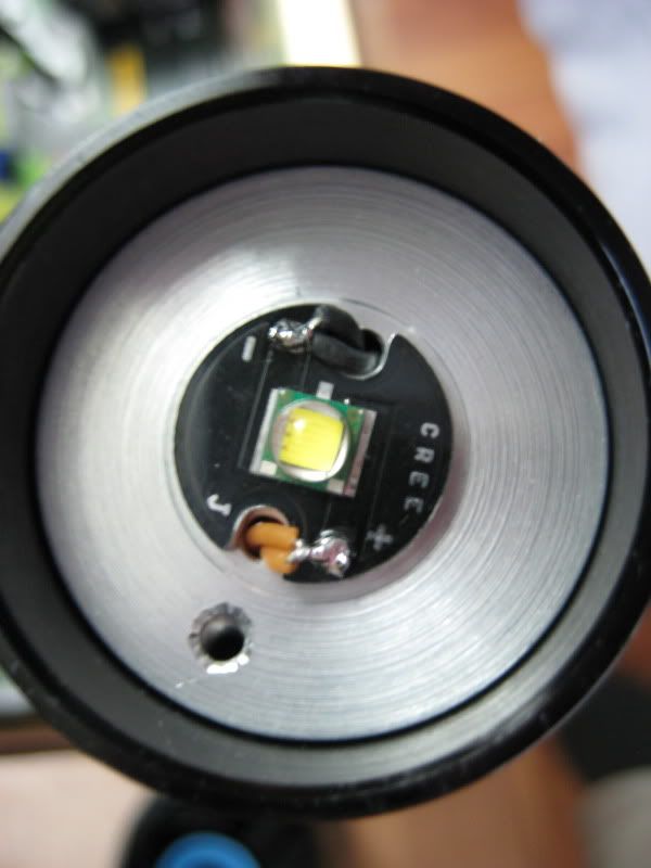
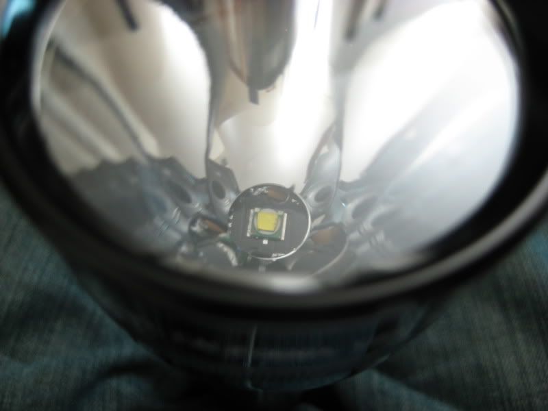
Reflector with LED in:
Complete and ready to light up!
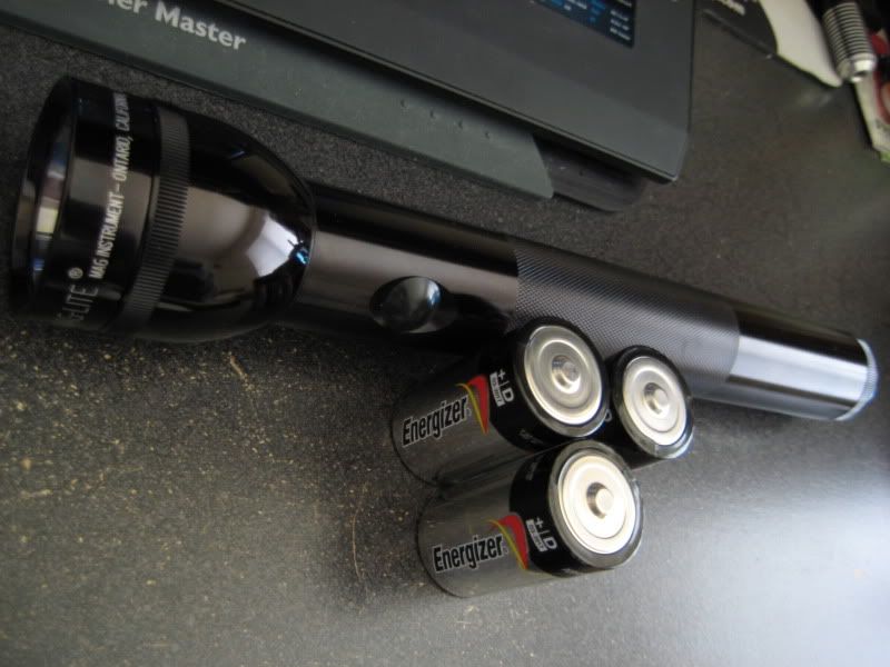
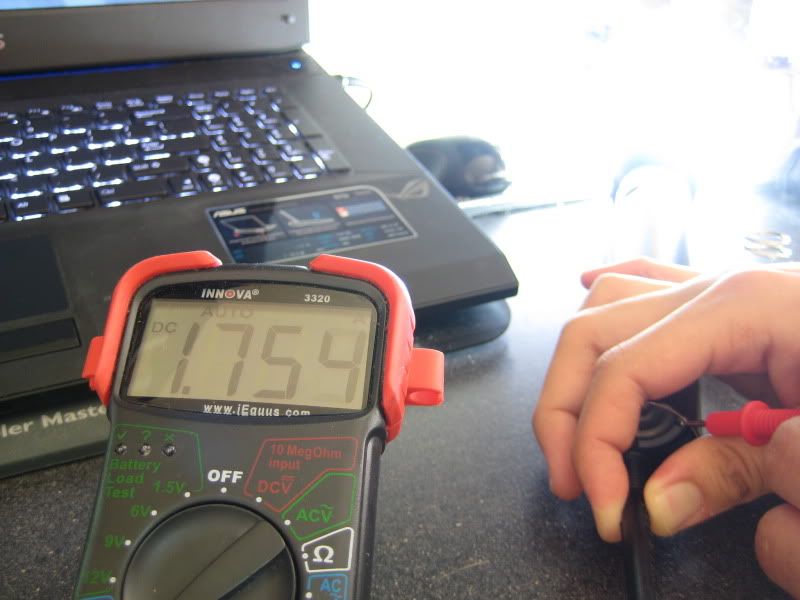
Initial test with 3 D alkaline cells. I was kind of disappointed, but I thought to add one more cell:
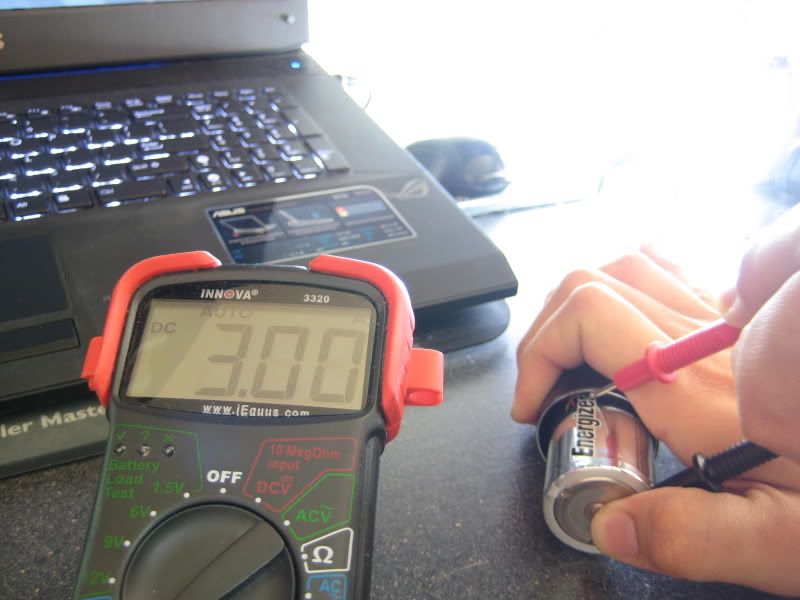
Using 4 D alkaline cells I got the specified current or close to it:
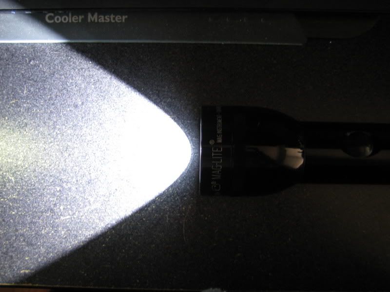
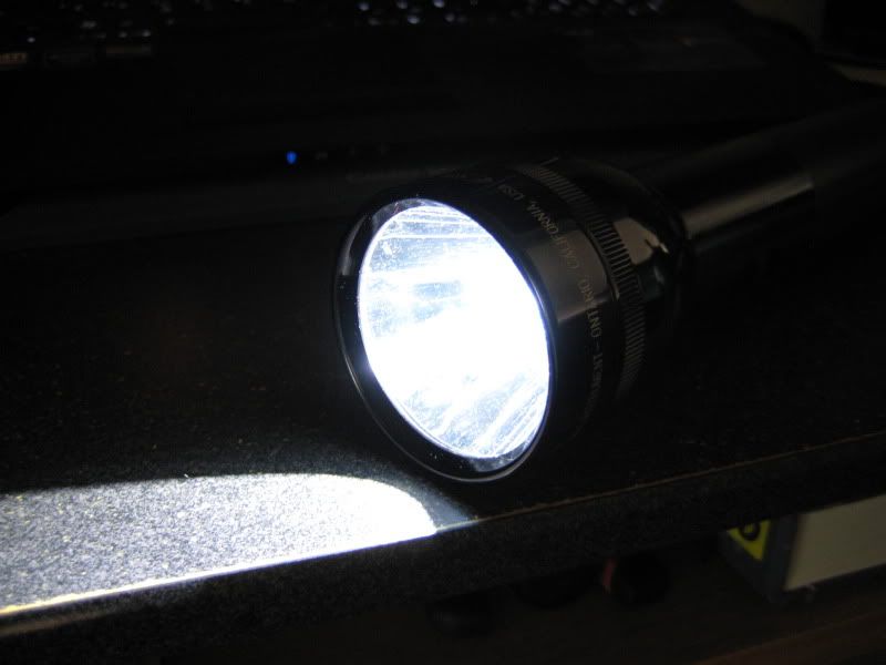
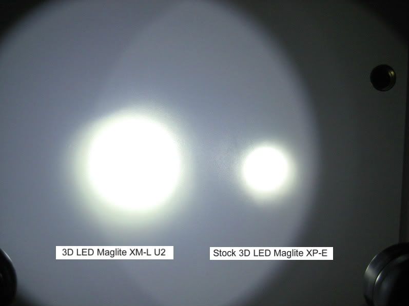
Light comparisons (My modded Maglite XM-L U2 vs Ultrafire TH-T60 XM-L T6 vs Stock 3D LED Maglite):
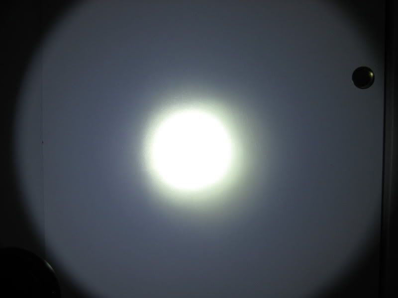
The spot is pretty nice and focused as you go in closer the black part of the star does show up so I'm thinking of getting some reflective material to fix that:
The pictures don't show it, but the U2 is clearly brighter. Now it could be that the OTF lumens is a lot brighter in the U2 bin because of the reflector gives it a tighter spot than the Ultrafire.
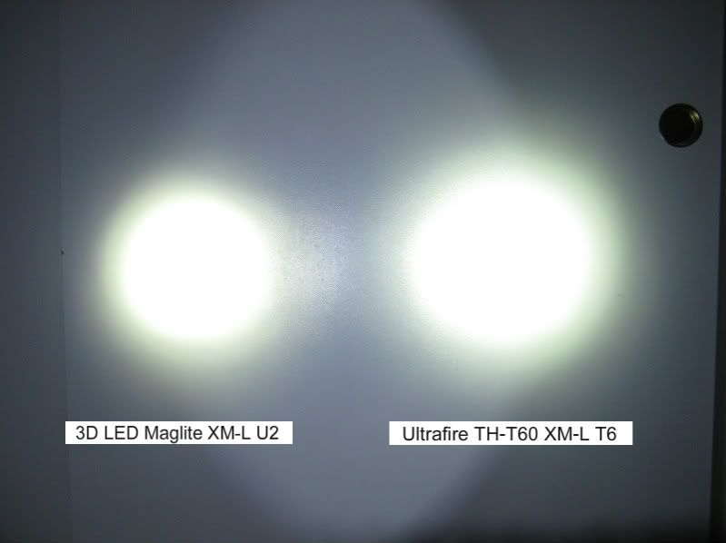
The stock LED Maglite has a tighter spot but is a lot dimmer than the U2 bin.
Conclusion:
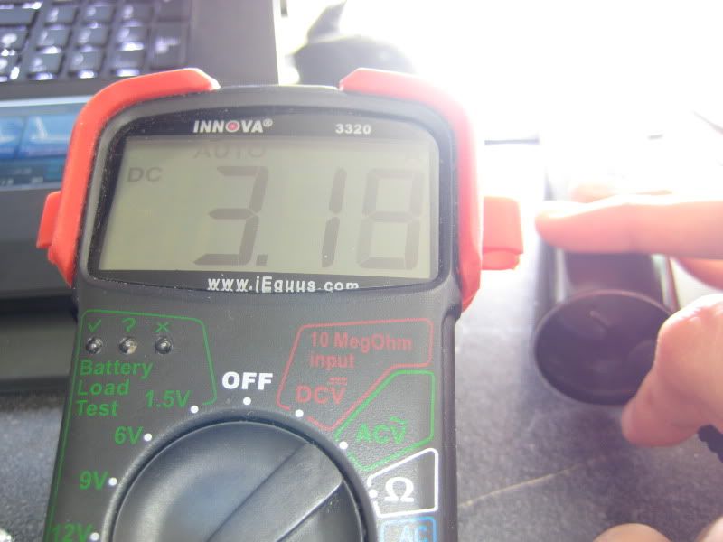
The pictures don't show it but the hotspot of the modded Maglite is a lot brighter than the Ultrafire. As I was testing the light I found the Vf to be around 3.15V driven @ 1.70A.
The 3 D cells didn't provide enough voltage/current to the driver (total of 1.6V x 3 = 4.8V) as I was only getting only a max of 1.76A. However,I did try using 4 D cells and that seemed to do the trick and current output was at 3.05A, so I might transfer this light into a 4D Mag to get the right current out. The driver doesn't feel hot when powering it with the 4 D cells.
I do want to note that the brightness between 1.76A and 3.05A looked almost the same to me, only a Lux meter can show the real difference.
LED burn in lowered the Vf of the U2 because after testing the current output was about 1.86A after 10mins of testing the light off and on. Over-driving these XM-Ls shouldn't be too much of a problem because there have been some cases of people driving these upwards to 3.5A - 4A
Happy New Years Everyone!
- CREE XM-L 6500k - 7000k U2 bin from DX *link*
- 3D LED Maglite (Black Friday sale @ Lowe's for $15!)
- Sandwiched AMC 7135 1050mA drivers x 3 for total of 3150mA output
- 1 mode: high
- Powered by 3 D alkaline cells
- Huge heat sink made by Jayrob!
- Dremeled stock reflector to fit
The CREE XM-L U2 bin is the highest and brightest, supposedly there is a U3 bin, but I haven't encountered any yet. It claims a 320 Lumen/W efficacy vs the common T6 at 300 Lumen/W (both driven at 100% @ 700mA). The fact that it came from DX can be sketchy, but I'll just have to take their word for it.
Flashlight pics:
I first Thermally epoxied the LED star on the heat sink made by jayrob, awesome job BTW! I let it cure overnight while I worked on the other components:
Removed the diodes and replaced with a jumper wire to bridge the connection:
I sandwiched them together and broke off a section to isolate the LED - of the driver for easier connection. The extra wire sticking out will be cut off:
Sandwiched driver should be outputting 3.15A given the right amount of voltage since it is a linear driver:
Switch prep using a Torx T8:
Dremeled the stock holder and sanded:
Added a twisted pair of silicone wire where it will connect to the driver:
Dremeled and sanded the stock reflector to fit the base of the mounted LED:
Connected the driver to the LED and set it down and screwed in set screw:
Reflector with LED in:
Complete and ready to light up!
Initial test with 3 D alkaline cells. I was kind of disappointed, but I thought to add one more cell:
Using 4 D alkaline cells I got the specified current or close to it:
Light comparisons (My modded Maglite XM-L U2 vs Ultrafire TH-T60 XM-L T6 vs Stock 3D LED Maglite):
The spot is pretty nice and focused as you go in closer the black part of the star does show up so I'm thinking of getting some reflective material to fix that:
The pictures don't show it, but the U2 is clearly brighter. Now it could be that the OTF lumens is a lot brighter in the U2 bin because of the reflector gives it a tighter spot than the Ultrafire.
The stock LED Maglite has a tighter spot but is a lot dimmer than the U2 bin.
Conclusion:
The pictures don't show it but the hotspot of the modded Maglite is a lot brighter than the Ultrafire. As I was testing the light I found the Vf to be around 3.15V driven @ 1.70A.
The 3 D cells didn't provide enough voltage/current to the driver (total of 1.6V x 3 = 4.8V) as I was only getting only a max of 1.76A. However,I did try using 4 D cells and that seemed to do the trick and current output was at 3.05A, so I might transfer this light into a 4D Mag to get the right current out. The driver doesn't feel hot when powering it with the 4 D cells.
I do want to note that the brightness between 1.76A and 3.05A looked almost the same to me, only a Lux meter can show the real difference.
LED burn in lowered the Vf of the U2 because after testing the current output was about 1.86A after 10mins of testing the light off and on. Over-driving these XM-Ls shouldn't be too much of a problem because there have been some cases of people driving these upwards to 3.5A - 4A
Happy New Years Everyone!


")