- Joined
- May 7, 2008
- Messages
- 545
- Points
- 0
This didnt start off as my original plan for this pointer upon receiving it. However it did play out as somewhat interesting.
I received my Arctic a few days ago and have been using it on and off for the last few days. Never leaving it on for more than a minute or two. Well two nights ago I was out star pointing and the darn pointer just turned right off. On a full charge none the less. I checked the battery, and even tried a few other 18650's I had laying around. This was all to no avail however.
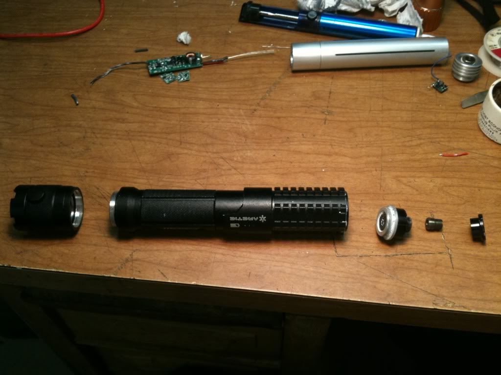
So I removed the end cap, and unscrewed the diode heatsink along with the diode and lens assembly. No loose wires, weird I thought. I pulled the diode and hooked it to my Dr. Lava Microboost driver set at 830mA. Nothing happened, not even the dim light of an LED'd diode. This was very strange. I proceeded to hook up a spare XJ-A140 diode to my Microboost just to make sure. It ran flawlessly. I repeated this procedure a few times until I came to the conclusion that this diode was shot. I also tested the Acrtic driver for output. It seemed to be running just find according to my multimeter. I knew at this point however that it would be nearly impossible for me to short the caps on the Acrtic driver and hook up a good diode. I tried as best as I could to locate and short any caps I could find but it was just too crowded in there. I left the pointer sitting for 24 hrs to try to wear down the caps. I experimented with a PHR 405nm diode just to play it safe and sure enough, it LED'd the diode even after being off for a full day. Running out of ideas and not willing to even attempt the up hill battle of shipping the thing back and trying to deal with a repair I bid to gut the beast.
I'd had some level of interest in doing this from day one. Just my nature to see the insides of things and figure out how they are built and how they work. My plan now is to machine a custom aixiz module heat sink adapter with correct nominal threads that I can simply screw it into the host. With how far the threads descend into the body of the host, it will leave a significant amount of room for the corrective optics I have plans for.
So in the long run, this pointer will turn out to be a better quality build, have better beam specs, and be more adjustable than it originally came. The battery indicator lights wont work, but I'm ok with that.
One note on the quality of the Arctic build, it's complete garbage. Many of the the components meant to screw into each other simply dont even thread into one another. You can pull some of the parts away from one another barley having to even unscrew them.
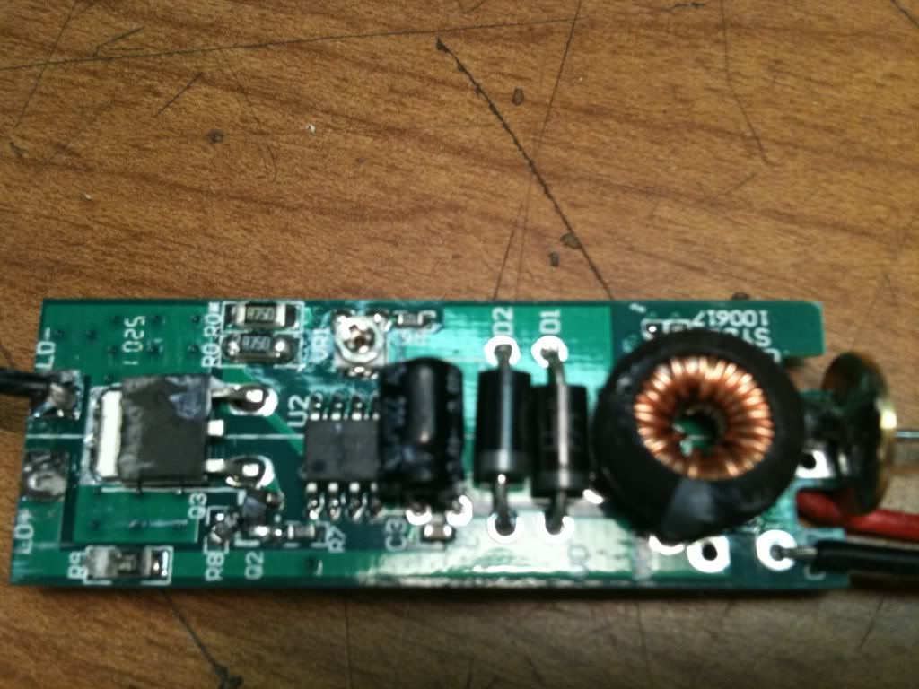
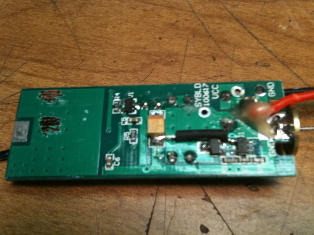
Here are the pictures. The large PCB is the main driver, the smaller one is the driver that illuminates the battery indicator holes. The smaller drive has a spring on it that I believe is used to contact the host to direct the positive battery end into the main driver. The small driver sits under the "ARCTIC" logo. On my pointer, you can simply turn this component to expose the PCB board.
oh, and upon removing the smaller driver it broke in half.


