- Joined
- May 1, 2009
- Messages
- 181
- Points
- 28
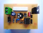
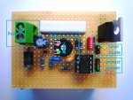
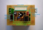
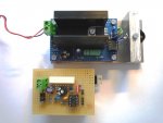
:thinking: Update: new more compact layout version 3 added
Hi folks,
in the past months there'd been tons of threads about high power constant current drivers for laser diodes (especially for our new friends the 445nm diodes).
More than a year ago I've developed a precise high power driver for 808nm laser diodes (capable to drive loads up to 8 amps). When I got my first 445nm diode I've tested the driver and it works fine with them. But the original 808nm schematic contains a lot of "unnecessary" protection and precision stuff you don't need for 445nm.
So, I've decided to build a simpler version for the 445nm diodes. Personally I don't like this LM317 based stuff (limited current range, expensive powerful pots required, too much energy is wasted into heat). And DIY switched current drivers are hard to handle for beginners.
Just take a look at the schematics I've attached. With the given resistor values the driver is capable to provide a constant current starting from *zero* 0mA up to 1250mA. With a lower value of the shunt resistor the driver can handle more than 8 amps at all!
HAVE FUN GUYS!!!
Questions? Remarks? Any interests in DIY kits? It's very easy for me to get all the required parts...
Yours,
Mojo
--------------------------------------------------------------------------
:thinking: Update: new more compact layout version 3 added
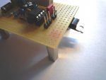
(more pictures see last reply)
--------------------------------------------------------------------------
TECHNICAL STUFF:
Supply voltage:
min. 6.5V for maximum current with R7 set to 1 Ohm
(or 7V with optional protection shottky diode)
Output current range:
0mA* - 1250mA with shunt resistor R7 set to 1 Ohm
0mA* - 2500mA with shunt resistor R7 set to 0.5 Ohm
* minor leakage of ~1mA may be possible
REMARKS:
The current is set with the pot. Before connecting the driver to the supply voltage always set the pot to *zero*. This is GND (pin 1=2 of pot).
Before connecting your expensive diode to the driver ALWAYS test with a dummy load first. A dummy load for laser diodes just can be build very very easy. Just put 5 or 6 standard diodes in series, connect them with the driver, power up and measure the current.
(+) -->|-->|-->|-->|-->|-- (-)
To measure the current just connect a voltmeter in parallel to R7. With R7 set to 1 Ohm each mV measured corresponds to exactly 1mA current. You can also connect a current meter in series to the voltage supply. Just subtract the current required for the driver itself.
The optional schottky diode protects the driver and *your laser diode* in case of the supply voltage connected with wrong polarity. But you'll also lose about 0.5V which have to be added to the supply voltage.
Add good heat sink for the mosfet (Q2, IRF520) is required. In my second prototype I just used the massive aluminum base plate of my laser build. The shunt resistor will also be quite hot during operation!
If you can't get the IRF520 you can also use a similar type (must be of type N).
All the capacitors are not required but without them it might be possible that some current spikes may occur (and your diode doesn't like spikes at all). Personally, I would never remove C2.
The opamp used for the driver is dual one (two similar opamps in one package). To avoid any unwanted oscillations just connect the remaining pins as shown in the schematic.
R8 is not required. But it will ensure that C4 is discharged when connecting a laser diode.
Most of the voltage is lost in R7 (1V at 1A current). If you choose a smaller resistor value less voltage is lost at same current (e.g. 0.5 Ohm -> 0.5V at 1A). The required supply voltage can be reduced then and less power is wasted into heat! ALWAYS TEST WITH A DUMMY LOAD!
Be aware of the fact that the diode is directly connected to the positive voltage supply and not grounded! But as far as I know the cases of the 445nm diodes are isolated from the diode itself.
PART LIST:
R1 - 1k Ohm (limit current for zener diode)
R2 - 15k Ohm
R3 - 10k Ohm
R4 - 1k Ohm
R5 - 100 Ohm
R6 - 1k Ohm
R7 - 0.56 Ohm / 1W minimum!
R8 - 10k Ohm
C1 - 10uF (optional)
C2 - 1nF (recommended)
C3 - 47pF (optional)
C4 - 100nF (optional)
D1 - Zener Diode 2.7V / 500mW
DS1 - Schottky Diode SB320 (or any other standard type with 2A or more)
Q2 - Power Mosfet N-Type IRF520N (or similar type)
IC1A/2B - Opamp TS912 (rail-to-rail)
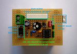
To build your own driver just use a drilled copper breadboard and a lot of solder...
Hi folks,
in the past months there'd been tons of threads about high power constant current drivers for laser diodes (especially for our new friends the 445nm diodes).
More than a year ago I've developed a precise high power driver for 808nm laser diodes (capable to drive loads up to 8 amps). When I got my first 445nm diode I've tested the driver and it works fine with them. But the original 808nm schematic contains a lot of "unnecessary" protection and precision stuff you don't need for 445nm.
So, I've decided to build a simpler version for the 445nm diodes. Personally I don't like this LM317 based stuff (limited current range, expensive powerful pots required, too much energy is wasted into heat). And DIY switched current drivers are hard to handle for beginners.
Just take a look at the schematics I've attached. With the given resistor values the driver is capable to provide a constant current starting from *zero* 0mA up to 1250mA. With a lower value of the shunt resistor the driver can handle more than 8 amps at all!
HAVE FUN GUYS!!!
Questions? Remarks? Any interests in DIY kits? It's very easy for me to get all the required parts...
Yours,
Mojo
--------------------------------------------------------------------------
:thinking: Update: new more compact layout version 3 added
(more pictures see last reply)

--------------------------------------------------------------------------
TECHNICAL STUFF:
Supply voltage:
min. 6.5V for maximum current with R7 set to 1 Ohm
(or 7V with optional protection shottky diode)
Output current range:
0mA* - 1250mA with shunt resistor R7 set to 1 Ohm
0mA* - 2500mA with shunt resistor R7 set to 0.5 Ohm
* minor leakage of ~1mA may be possible
REMARKS:
The current is set with the pot. Before connecting the driver to the supply voltage always set the pot to *zero*. This is GND (pin 1=2 of pot).
Before connecting your expensive diode to the driver ALWAYS test with a dummy load first. A dummy load for laser diodes just can be build very very easy. Just put 5 or 6 standard diodes in series, connect them with the driver, power up and measure the current.
(+) -->|-->|-->|-->|-->|-- (-)
To measure the current just connect a voltmeter in parallel to R7. With R7 set to 1 Ohm each mV measured corresponds to exactly 1mA current. You can also connect a current meter in series to the voltage supply. Just subtract the current required for the driver itself.
The optional schottky diode protects the driver and *your laser diode* in case of the supply voltage connected with wrong polarity. But you'll also lose about 0.5V which have to be added to the supply voltage.
Add good heat sink for the mosfet (Q2, IRF520) is required. In my second prototype I just used the massive aluminum base plate of my laser build. The shunt resistor will also be quite hot during operation!
If you can't get the IRF520 you can also use a similar type (must be of type N).
All the capacitors are not required but without them it might be possible that some current spikes may occur (and your diode doesn't like spikes at all). Personally, I would never remove C2.
The opamp used for the driver is dual one (two similar opamps in one package). To avoid any unwanted oscillations just connect the remaining pins as shown in the schematic.
R8 is not required. But it will ensure that C4 is discharged when connecting a laser diode.
Most of the voltage is lost in R7 (1V at 1A current). If you choose a smaller resistor value less voltage is lost at same current (e.g. 0.5 Ohm -> 0.5V at 1A). The required supply voltage can be reduced then and less power is wasted into heat! ALWAYS TEST WITH A DUMMY LOAD!
Be aware of the fact that the diode is directly connected to the positive voltage supply and not grounded! But as far as I know the cases of the 445nm diodes are isolated from the diode itself.
PART LIST:
R1 - 1k Ohm (limit current for zener diode)
R2 - 15k Ohm
R3 - 10k Ohm
R4 - 1k Ohm
R5 - 100 Ohm
R6 - 1k Ohm
R7 - 0.56 Ohm / 1W minimum!
R8 - 10k Ohm
C1 - 10uF (optional)
C2 - 1nF (recommended)
C3 - 47pF (optional)
C4 - 100nF (optional)
D1 - Zener Diode 2.7V / 500mW
DS1 - Schottky Diode SB320 (or any other standard type with 2A or more)
Q2 - Power Mosfet N-Type IRF520N (or similar type)
IC1A/2B - Opamp TS912 (rail-to-rail)
To build your own driver just use a drilled copper breadboard and a lot of solder...
Attachments
Last edited:


