LPF Donation via Stripe | LPF Donation - Other Methods
Links below open in new window
ArcticMyst Security by Avery


You are using an out of date browser. It may not display this or other websites correctly.
You should upgrade or use an alternative browser.
You should upgrade or use an alternative browser.
The real high power and full range DIY laser diode driver *new version 3*
- Thread starter mojo_1234
- Start date


D
Deleted member 8382
Guest
Re: The real high power and full range DIY laser diode driver *updated!*
Great circuit. You shouldn't care too much about size, I hope noone is trying to make a 1W pen pointer")
Great circuit. You shouldn't care too much about size, I hope noone is trying to make a 1W pen pointer
- Joined
- May 1, 2009
- Messages
- 181
- Points
- 28
Re: The real high power and full range DIY laser diode driver *updated!*
Thanks :wave: !!! You're right!!! I would be scared to have a 12 years old neighbor with a 1000mW pointer playing around (hey! look! a damned bright living room :san: oh... there's someone standing around...)
To add an analog input for modulation - no problem... I'm already in discussion with another board member for this!
The ILDA specs define a 0V (off) to 5V (100%) signal to modulate intensity, right?
Any help appreciated!
mojo
Re: The real high power and full range DIY laser diode driver *updated!*
Correct on the 5v analog modulation input.
You're my hero! I'll buy a round if it works :beer:
Just to make sure... not TTL/PWM, but true analog modulation
Closest I have come yet is asking newark if they might be able to help finish a schematic based on one of these IC's:
http://www.newark.com/jsp/search/br...e&locale=en_US&catalogId=&prevNValues=1004008
Last edited:
hakzaw1
0
- Joined
- Apr 2, 2009
- Messages
- 10,662
- Points
- 113
Re: The real high power and full range DIY laser diode driver *updated!*
Great Thread-- lots of added info from others too--just in time for those 445 labbies
+rep for the good job
a kit sounds great too
Great Thread-- lots of added info from others too--just in time for those 445 labbies
+rep for the good job
a kit sounds great too
- Joined
- May 1, 2009
- Messages
- 181
- Points
- 28
Re: The real high power and full range DIY laser diode driver *updated!*
Stay tuned!
I'm already working on a version with input for analog modulation. Also looking for a proffesional PCB service to get rid of this breadboard stuff (for me it's ok but not for a kit....)
Updates comming soon...
Stay tuned!
I'm already working on a version with input for analog modulation. Also looking for a proffesional PCB service to get rid of this breadboard stuff (for me it's ok but not for a kit....)
Updates comming soon...
- Joined
- Dec 23, 2007
- Messages
- 2,494
- Points
- 0
Re: The real high power and full range DIY laser diode driver *updated!*
You said this is capable of 8A? What resistor value would someone use to get a full 8A from this driver?
You said this is capable of 8A? What resistor value would someone use to get a full 8A from this driver?
- Joined
- May 1, 2009
- Messages
- 181
- Points
- 28
Re: The real high power and full range DIY laser diode driver *updated!*
If you refer to the latest version 3 of the schematic you'll require a shunt resistor of about ~0.1 Ohm. With version 3 I've reduced the reference voltage to 2.7V. The resistor and pot network reduces it down to ~0.7V. So, with a 0.1Ohm shunt resistor it should be possible to get around 8A out of the driver....
Please also take a look into my last reply. It's very important to know about the maximum thermal power loss of the circuit...
- Joined
- May 1, 2009
- Messages
- 181
- Points
- 28
Re: The real high power and full range DIY laser diode driver *updated!*
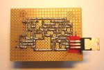
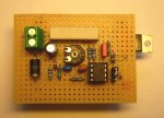
Here are the details of the new version 3. I've also added some details about the layout...

The overall heat produced by the power mosfet can be calculated with the following formula:
Ptot = (Usupply – Udiode – 0.56Ωshunt * Idiode) * Idiode
e.g. with 12 V of supply, 1 A of current and a LD with around 4.5V (e.g. blue ray or 445nm) a total power of 6.94 Watt has to be handled by the heat sink. Ptot.max is around 30 Watt (yes, the datasheet talks about 50 Watt... but...:beer
Stay tuned! More will come soon...
mojo
Here are the details of the new version 3. I've also added some details about the layout...
The overall heat produced by the power mosfet can be calculated with the following formula:
Ptot = (Usupply – Udiode – 0.56Ωshunt * Idiode) * Idiode
e.g. with 12 V of supply, 1 A of current and a LD with around 4.5V (e.g. blue ray or 445nm) a total power of 6.94 Watt has to be handled by the heat sink. Ptot.max is around 30 Watt (yes, the datasheet talks about 50 Watt... but...:beer
Stay tuned! More will come soon...
mojo
Attachments
- Joined
- Dec 29, 2009
- Messages
- 3,136
- Points
- 63
I heard mention of a kit. Just displaying my non-committing interest if the kit includes an actual etched copper clad board. Kits are fun, and it would be even more fun to end up with something you can use, instead of two red LEDs that blink back and forth. I mean, what are you gonna do with that?! But yeah, kit would be sweet =)
- Joined
- Jan 11, 2008
- Messages
- 671
- Points
- 0
Blinking LEDs are always funI heard mention of a kit. Just displaying my non-committing interest if the kit includes an actual etched copper clad board. Kits are fun, and it would be even more fun to end up with something you can use, instead of two red LEDs that blink back and forth. I mean, what are you gonna do with that?! But yeah, kit would be sweet =)

On topic: I might breadboard your driver tonight to try it out.
HIMNL9
0
- Joined
- May 26, 2009
- Messages
- 5,318
- Points
- 0
^ A potentiometer .....
Hook a 10Kohm pot from GND and +5V, and connect the central pin to the analog input (through a 2 or 3 K resistor, if you want to be sure), and if the analog mod works, you must be able to change the output power from zero to max just turning the potentiometer ..... don't know a more easy way, for check it
Hook a 10Kohm pot from GND and +5V, and connect the central pin to the analog input (through a 2 or 3 K resistor, if you want to be sure), and if the analog mod works, you must be able to change the output power from zero to max just turning the potentiometer ..... don't know a more easy way, for check it
- Joined
- May 1, 2009
- Messages
- 181
- Points
- 28
You're not the only one :yh:
I'm already looking for a cheap board service. Thanks for your interest....
I'm already looking for a cheap board service. Thanks for your interest....
I heard mention of a kit. Just displaying my non-committing interest if the kit includes an actual etched copper clad board. Kits are fun, and it would be even more fun to end up with something you can use, instead of two red LEDs that blink back and forth. I mean, what are you gonna do with that?! But yeah, kit would be sweet =)
- Joined
- May 1, 2009
- Messages
- 181
- Points
- 28
If you have a analog signal, e.g. from 0V to 5V, you can use it for the reference voltage. But it has to be adjusted to the voltage provided by the shunt resistor.
Example:
Usignal = 0V to 5V
Rshunt = 0.56Ohm
Idiode = 1A
With the given parameters Ushunt is around 0.56V for 1A. This means the opamp has to be feed with 0.56V. When your analog signal is max. 5V a simple resitor network will work (e.g. 1kOhm and 10kOhm).
Please also add a simple diode (Ud ~0.7V) connected to ground behind the resistor network. This protects both the opamp input and your diode if the analog signal voltage gets too high.
If you have a dual channel oscilloscope just measure the analog input and the voltage drop of the shunt resistor. Take care to use the common ground for reference. The oscilloscope should not show any spikes...
IMPORTANT!
The current driver layout was not designed for high frequency input signals. The current provided by the opamp to charge/discharge the gate of the mosfet is not high enough to safely handle frequencies higher than 1kHz.
Some other board members have asked me for an ILDA version for modulation frequencies up to 100kHz. I'm working on this...
(with additional opamp to buffer input signal and support for differential ILDA signals)
Update is comming soon...
mojo
What is the best way to test analog modulation without a DAC / ilda controller?
I have an oscilloscope but not sure what to use for analog input.
^ A potentiometer .....
Hook a 10Kohm pot from GND and +5V, and connect the central pin to the analog input (through a 2 or 3 K resistor, if you want to be sure), and if the analog mod works, you must be able to change the output power from zero to max just turning the potentiometer ..... don't know a more easy way, for check it
Last edited:
My DC power supply is adjustable but jumps from 4.5v to 6vdc @ 1amp.
From the DC PSU I hooked + to one side of a 10k pot and - to the other side of the 10k pot... the middle pin I connected to a 1kohm resistor. The other side of the resistor was then connected to the analog mod input but doesnt seem to be doing anything at either 4.5v or 6v.
I misinterpret something?
