- Joined
- Jan 7, 2007
- Messages
- 6,309
- Points
- 83
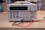
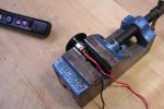
It could also be bad connections at this current level. I need to check it with my power supply. The cells I have are from Wicked and easily put out a couple amps. This starts in 5 seconds. I really didn't want this much current.
HMike
HMike


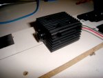
 Being "old school, I assume that ground carries through a power supply circuit. DrLava clearly states that the gorund (-) does not carry through on his board. I got in a hurry and connected ground wires where they were convenient and put battery ground on the diode - port. DON'T do that --